

Overview:
Most of the older PHI AES systems use a voltage to frequency converter (V/F) to convert the electron multiplier auger signal output from a small current into a frequency so that the computer can count the signal. At the time these systems were designed, this was a more cost effective approach than using a high resolution A/D converter.
This document explains the procedure for testing the following V/F preamplifiers:
PHI 96
PHI 96A
PHI 96B
RBD V/F-4
Equipment needed:
(1) 30meg ohm resistor (or three 10 Meg ohm resistors soldered together)
(2) Clip Leads
(1) Computer with AugerScan
(1) Oscilloscope (optional)
(1) 4 foot BNC to BNC Cable (optional)
(1) 32-100 Multiplier Supply
Note:
The V/F Preamplifiers used on PHI systems convert the current through the electron multiplier into a frequency. The maximum current is negative 500 nA. By using a 30 Meg ohm resistor (with negative 15 volts DC applied = negative 500nA) , the negative 500 nA can be applied to the collector input without the use of a DC current source, and the V/F preamplifier easily tested.
Caution! Refer servicing of electronic units to qualified personnel.
(If this procedure is followed exactly, no high voltage will be applied to the V/F preamplifier)
Procedure:
- Turn the power off on the 32-100 electron multiplier supply.
- IMPORTANT! Remove the HV POS IN, HV POS OUT and COL cables from the V/F preamplifier. This will prevent any high voltage from being applied to the preamplifier during testing.
- Set the CMA multiplier switch to OFF.
- Remove the cover from the V/F preamplifier:
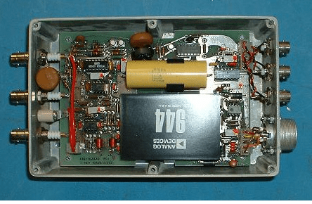
”
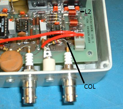
- Locate the “Collector” (J4) connection:

- “Jumper” a 30 Meg ohm resistor between L2 (floating minus 15 volt supply) and the COL lead (J4):
- Set up AugerScan to acquire a survey in the V/F mode. Make sure that V/F 1 is selected in the hardware properties and that the Auto EMS is not checked in the multiplier properties dialog box. This will force the input into the V/F mode.
- Turn on the 32-100 electron multiplier supply. The CMA high voltage switch should be in the OFF position. Setting the CMA voltage switch to OFF will ensure that no high voltage will be applied to the V/F preamplifier during the test. (And the cables are also disconnected)
- Acquire the survey and compare the results with the table below. If you disconnect the test resistor after the survey is about half way through then you should see the counts drop to just a few thousand CPS.
| You should have approximately the following counts displayed in AugerScan: V/F preamplifier model number | Maximum V/F counts per second |
| PHI 96 | 100 kHz |
| PHI 96A | 1 mHz |
| PHI 96B | 1 mHz |
| RBD V/F-4 | 4 mHz |
OPTIONAL – If you have an oscilloscope you can also look at the frequency output connector of the V/F preamplifier, Just connect a BNC cable between your oscilloscope and the Frequency output connector of the V/F preamplifier.
If the frequency output is approximately the value shown in the table above, then your preamplifier is working properly. If not, RBD Instruments provides repair services and loaner V/F preamplifiers.
When finished testing, turn off the 32-100 and replace the cables to the V/F preamplifier and set the 32-100 switch to where it was before testing (typically it is set to digital).
BONUS – Here is a link to the 96A Manual, which is the most common V/F preamplifier used on older PHI AES systems. If you have a 96B or VF4 contact RBD Instruments.

The test procedure for 96A V/f preamplifier is very helpful.