Ion gauges work by using a hot tungsten filament to ionize gas molecules and then collect the ion current and convert that current to a reading in Torr, Pascal or millibar.
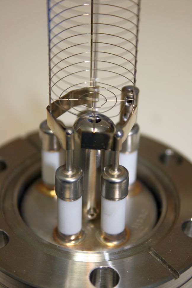
Over time the ceramics on the ion gauge feedthrough can become coated with tungsten or titanium. That coating is conductive and when the coating covers the entire length of the feedthrough then the resulting leakage current can affect the accuracy of the ion gauge or prevent it from working at all. The picture below shows an example of a coated ion gauge.

Usually once the ceramics are fully coated then the ion gauge needs to be replaced at a cost of $500.00 or more.
This blog post will show you how to remove the coating from the ceramics and restore normal operation of the ion gauge for about $15.00
The first thing that you will need to do is to buy some dental polishing tape. I used some TDV diamond strips as shown below. You can get diamond polishing tape on Amazon.

With the filaments removed from the ion gauge, mount the ion gauge in a vise. The ion gauge needs to be tight but not so tight that the flange warps.

Use the diamond strip in a back-and-forth motion to remove the coating from the ceramic. Use a light touch as you want to remove the coating but not eat away at the ceramic any more than necessary.

Once you have the ceramic cleaned off, use a soft paint brush to clean the grid and to remove any small bits of ceramic from the flange. Note that all of the deposition does not need to be removed, but you want enough so that there is a gap on the ceramics which will eliminate any leakage current. The picture below shows the results after a few minutes of cleaning. Not very pretty, bit it does restore functionality.


Install a new filament set and you are good to go! RBD Instruments sells ion gauge filaments for the PHI DGCIII controller. Contact us for more information.