

Progamming the 9103 Picoammeter
RBD’s 9103 USB PIcoammeter is packaged with Windows application software for control, current display, data-logging, and graphing. However, it’s often desirable to use the 9103 with other operating systems, integrate it with other hardware or software systems, and/or extend the capabilities of the application software. Fortunately, the 9103 utilizes an ASCII command set that exposes all of its features. Programming the 9103 Picoammeter is straightforward and easy to test.
A complete guide to programming the 9103 picoammeter can be viewed and downloaded from RBD’s website here. This post will give you an overview of setting up communications with the 9103 and the message structure for controlling the unit and gathering status and data.
Of course, every programming environment is different. As long as you are working with a tool that supports USB communication and text streaming, you can create a custom application for your 9103.
Setting up Communications
If you are using your 9103 with Windows, the installed driver creates a virtual serial COM port. RBD’s Actuel application software uses this port for communicating with the 9103, and any application you use to interface with the 9103 will use this same port for communications.
For other operating systems, you’ll need to download the appropriate driver from the manufacturer of the USB communications components, FTDI. Those drivers can be found here.
If you are interfacing the 9103 with LabView, drivers and scripts can be found on the 9103 downloads page.
Communications Protocol
The communications protocol for the 9103 is typical for many serial devices. Whether you configure the USB port using your operating system or program it within your application, the protocol is as follows:
|
Setting |
Value |
|
Bits per Second (Baud Rate) |
57600 |
|
Data Bits |
8 |
|
Parity |
None |
|
Stop Bits |
1 |
|
Flow Control |
None |
Sending and Receiving Commands
Communication with the 9103 is asynchronous. Most commands sent from the computer control device to the Picoammeter will be answered with a response, which may include an error message if there is a problem understanding/executing the command.
All messages are delivered as ASCII text – there is no binary message data. This includes the actual data delivered by the 9103, which is a formatted ASCII value.
Depending on your programming environment and application, you’ll normally be coding (at the least) logic to deliver the messages to the 9103, as well as to monitor the USB port and parse incoming messages.
Message Formats and Sample Messages
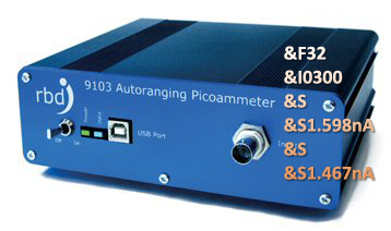
All messages are preceded by the “&” character, followed by a single character denoting the command or data type, as well as additional characters representing command parameters or data.
Here are a few examples:
| I – From PC, command message to set the data sample interval, parameter is in milliseconds, 0015 to 9999.Example: ‘&I0500‘ sets the sampling interval to 500 milliseconds |
| F – From PC, controls the filter settings for the sample data. Allowed values are 000, 002, 004, 008, 016, 032, and 064.Example: ‘&F016‘ sets the filter value to 16 |
Data and status are passed back to the PC from the 9103 using a similar format. For example:
| E – From device, sent if there was an error. Includes string description of error. |
A full description of the command and data messages, as well as additional information on programming the 9103 Picoammeter are found in the 9103 User Guide.
Using Actuel’s Console Window For Debugging
If you are communicating with the 9103 using Windows, you can view the communications taking place in real-time using the Console window – simply click the Console button on the main window. You can also type commands here and see the results in real-time.

 Two exciting new features are
