A blog on the repair, operation and calibration of surface analysis systems and components including electron spectrometers, sputter ion guns and vacuum related hardware. Click on the Index tab below to see a list of all posts. Visit our website at http://www.rbdinstruments.com
While performing preventive maintenance on an X-ray photoelectron spectrometer recently I was reminded of how important the simple tasks are in preventing problems. On this particular system the card rack air filters were relatively clean and as a result of that, all of the boards in the card rack were dust free and clean. When we inspect the boards as part of a PM visit we often find that some of the components have attracted dust and dirt which in turn can cause arcing and damage on high voltage boards.
Here are some easy preventive maintenance tasks that you can perform yourself which will help to keep your X-ray photo electron, Auger electron spectroscopy or Secondary Ion Mass spectroscopy system running smoothly:
Clean the air filters on a regular basis. Depending on how dusty your lab is, that could mean once a month or once every 6 months. Be sure to turn the card rack power OFF and the fans OFF before you remove the air filters.
Keep the temperature in the room that your system is located cool at all times. For older surface analysis systems, 68 degrees F (20C) or lower is ideal. If the room temperature gets up to the mid to upper 70s F you can expect to have more component failures.
Vacuum out the back of the electronics console and the inside of the electronic units the same time that you clean the air filters.
Check the cooling fans in the electronics rack and inside any electronic power supply or control. If the fans are spinning slowly or not at all, replace them. Keeping air moving is very important for older electronics and can help to extend the lifetime of the electronic components inside.
These 4 simple tasks can prevent more serious problems from occurring. Then hopefully the only maintenance that your system may need will be the occasional replacement of consumable parts such as ionizers, filaments and electron multipliers.
RBD Instruments always performs these simple tasks as part of a PM visit. If you service your system yourself or have it serviced by another company, always insist that these tasks are performed during the preventative maintenance visit. The pictures below filters that were removed from a system that had been on service contract with another company. Obviously they had not been cleaned in a long time!
As the old Fram oil filter commercial in the 80’s said, you can pay me now or you can pay me later. The idea being that if you don’t change your automotive oil filter on a regular basis that it will end up costing you a lot more to fix your engine later. The same thing applies with any piece of expensive equipment. Do the simple preventive maintenance tasks on a regular basis and you will avoid most of the severe time consuming problems.
After a number of years it becomes necessary to replace the ion pump elements used on surface analysis instrumentation such as X-ray Photoelectron spectrometers (XPS), Auger (AES), and Secondary Ion Mass spectrometers (SIMS). But what if you can’t afford the cost of new ion pump elements? Depending on how worn out the plates are, you may simply be able to “flip” the plates.
This procedure is written for the DI (Differential Ion) pump elements used on most PHI surface analysis and Perkin Elmer vacuum systems. However, it can also be applied to other ion pump elements such as Varian, which are used on many general-purpose vacuum systems.
Ion pump elements have three basic components: magnets, an anode, and two cathodes. For the DI pumps, one cathode plate is made out of tantalum and the other cathode plate is made out of titanium. Using cathodes made from these two materials provides good pumping stability for both inert and active gases. The size of the pump is determined by the number of elements used. For example, a Perkin-Elmer 120 l/s ion pump has 4 elements and a 220 l/s ion pump has 8 elements.
Ion pump element
The magnets cause electrons, which are created as part of the ionization process, to spiral in the anode. This in turn increases the probability of a collision with a gas molecule. When an electron collides with a gas molecule, the gas becomes ionized and the molecule is accelerated into a cathode. Over time, the cathodes become sputtered away and the ceramics that isolate the anode become coated and conductive. Also, flakes can form and accumulate, which can cause arcing from the anode to ground. As a result, the pump elements’ performance is greatly reduced and the elements need to be removed and inspected.
Usually, the pump elements need to be replaced. However, if the plates are not sputtered all the way through, it is possible to simply “flip” the plates, clean the anode, and replace the anode-isolation ceramics. Functionally, the ion pumps will be good as new. They will not last as long as new ion pump elements because the plates will not be as thick as new elements. You can, though, often get an extra 2-to-5 years of usage from the elements depending on your base vacuum, gas load, etc.
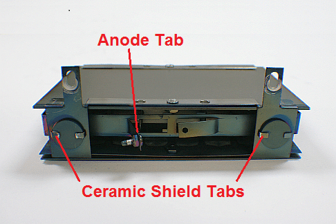
In the image below, you can see the anode, cathodes, and the heavily coated anode-isolation ceramics. Before you disassemble the elements, make a note of the position of the anode tab. One of the elements usually has the tab on the opposite side from the others. You will reassemble the elements so the tab is in the same location.
Coated ion pump element
Disassembling and Reassembling the Ion Pump Elements
Wear gloves and use clean tools when disassembling and reassembling the ion pump elements.
Use a slotted screwdriver and a 5/16″ open end wrench to remove the screws and nuts that hold the elements together. TIP: Use isopropanol as a lubricant to prevent the nuts from seizing.
Use a small flat-tip screwdriver and a pair of pliers to bend the ceramic shield tabs up.
Lift each ceramic shield out of its support bracket to remove the anode-isolation ceramics.
The graphic below shows the components once the pump elements have been disassembled: the anode plate, the cathode plates, and the support brackets
.
The image below shows the cathode after it has been sputtered. The sputtered areas look like pin holes. In this example, the sputtering is only about ½ of the way through the plate, which means that there is a lot of material left.
Sputtered ion pump cathode plate
As shown in the picture below, we can see that the cathode is not sputtered all the way through when we flip it over; there are no holes on this side of the cathode. Because the center of the sputtered area will most likely not line up perfectly when the plate is flipped, the lifetime of the pump will be extended.
Un-sputtered ion pump cathode
The picture below is an example of a plate that is sputtered all the way through. In this case, the ion pump elements need to be replaced and not rebuilt.
Sputtered ion pump cathode
The picture below shows a clean ceramic and a coated ceramic. RBD Instruments provides the new ceramics. Please visit the Parts – Vacuum related section of our website at www.rbdinstruments.com.
Ion pump ceramics
Once you have disassembled the elements, the rebuild procedure is very simple:
While wearing gloves, use a clean wire brush to remove any flakes from the plates, anode, support brackets, and ceramic shields. Note that you do not need to remove all of the deposits and discoloration on the parts. Just make sure that whatever remains will not come off easily. The important thing is that the active portion of the plates is now fresh, the ceramics are new, and there are no loose flakes that can cause shorting.
Install new ceramics. TIP Use a channel lock pliers to crimp the tabs on the ceramic shields that hold the ceramics in place.
Flip the plates so that the fresh side is facing the anode. Because the tantalum plate is thinner the titanium plate, most elements will have a thin steel plate on the tantalum side of the cathode. The tantalum plate will be noticeably heavier than the steel plate.
Make sure that you put the clean tantalum side towards the anode. The picture below shows the dirty element after the plates have been flipped and reassembled. It may not look pretty, but it will work as well as a new element.
Rebuilt ion pump element with flipped plates
Assemble the plates and support brackets, as shown in the picture above. Make sure that the support brackets are holding the anode snuggly as you tighten the screws and nuts.
Installing the Elements Back into the Pump Well
Before installing your rebuilt or new ion pump elements, use a wire brush and a vacuum cleaner to clean the pump well and remove all flakes that are inside the pump well. You can also wipe the inside of the pump well with a Kim wipe or lint-free cloth and some isopropanol. You want the pump well to be as clean as possible as any remaining flakes can cause shorting in the elements, which would require that you disassemble the ion pump again.
If possible, bake your vacuum chamber into the turbo pump for 4 hours.
Let the ion pump cool down before you try to start the ion pumps. Removing as much water vapor as possible will make the ion pumps much easier to start.
Start the ion pump.
Pump the chamber until you are in low 10-7 or low 10-8 Torr range.
With the ion pumps on, bake the chamber again for an additional 8-to-24 hours.
If you need more information on this procedure or would like to order the ceramics or new ion pump elements, please contact us.
Here are some pictures that show an ion pump being lowered:
One of the more common questions that we get concerning the DGC III digital ion gauge control (also known as the DIG III) is how to enter the set point values. We created this video to demonstrate the basic operation of the DIG III including the set points. For advanced operations, please refer to the DGC III ion gauge manual.
The PHI DIGIII Digital ion gauge controller provides an indication of the vacuum in the chamber, as well as 4 set points which are used to interlock certain system functions. A common problem with the DIG III is that the set points reset to zero after the DIG III is turned off or loses power. In most cases, that problem is the result of a worn out DIGIII battery and is something that the user can easily replace themselves – just be aware that the battery is soldered onto the set point board inside the DIG III.
The RBD Instruments part number for the DIG III Set point battery is BA3.6RE.
These are the typical values used on most PHI surface analysis systems
After about 8 to 10 years, the set point operation can become intermittent due to oxidation of the contacts on K901 through K904 on the set point board.
Possible symptoms include:
The electronic card rack power drops out intermittently.
The X-ray source will not operate even though set point 3 indicates that it is on.
To repair this problem, simply remove the covers from the set point relays K901-K904 on the set point board and clean the contacts with some fine sandpaper or emery cloth.
For other more serious DIG III problems, RBD Instruments can repair or exchange your defective control. For more information visit our website or call us at 541-550-5016