

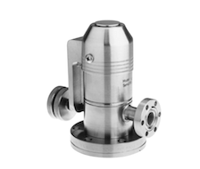
This post is about how to adjust the 951-5100 and 951-5106 Varian variable leak valve commonly found on vacuum chambers across the globe. Invented in 1968 by William Wheeler and Paul Hait, the patent was assigned to Varian Associates; many thousands of these valves have been built since then. In 2010, Varian was purchased by Agilent Technologies and since that time it has been harder to find the rebuilt kits for these variable leak valves. The order information for the rebuild kit can be found at the bottom of this post, as well as a link to the instruction manual.
Overview-
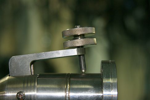
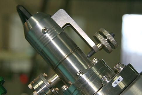
When this type of variable leak valve does not close all the way, operators will usually unlock the two knurled knobs and move them up the fine drive screw assembly and then re-lock them. What that does is to allow the handle to move out further from the valve body and put more pressure on the sapphire, which effectively closes the valve. That works fine for periodic adjustments to close the valve. However, if the handle is far away from the valve body it is possible to get too much leverage and crack the sapphire (which causes catastrophic valve failure) and also reduces the range of the valve arm. The picture below shows a valve handle that is too far away from the valve body and needs to be reset.
Adjustment procedure –
When properly adjusted, the handle will be parallel to the valve body when closed. Gas should just start to leak into the vacuum chamber when the knob is turned CCW by 2 full turns. The following procedure is an abbreviated version that I use which works most of the time. For a more thorough explanation of this adjustment refer to the manual.
CAUTION! Read and understand the procedure and notes before you attempt the adjustment on your system. You need to know exactly how much gas pressure you are putting into the valve, how much you need to adjust the valve by and the status of your vacuum chamber. The roughing screw is very sensitive; a very small amount of adjustment can be the difference between success and a dumped system!
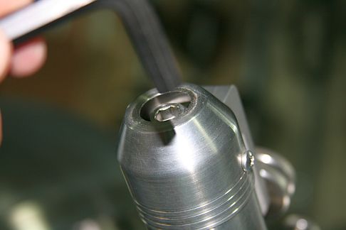
1. Use a small straight blade screwdriver to remove the hole cover on the back end of the leak valve to expose the roughing screw cap hex head.
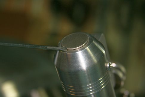
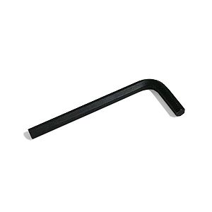
2. Insert a 5/16” Allen wrench into the cap head of the roughing screw
3. Monitor the vacuum in the chamber. For most PHI surface analysis systems the vacuum should be in the low 10-9 Torr or lower.
4. If necessary, adjust the handle so that it is parallel to the valve body. The knobs will need to be adjusted – turn the top knob CCW while holding the bottom knob in place. That will separate the two knobs and then you can spin them one at a time into position. Lock them on the fine drive screw assembly by holding the bottom knob in place and turning the top knob CW until it firmly butts up against the bottom knob. There is a spring washer between the two knobs that helps to lock them together. Once set, always turn both knobs together when opening (turn CCW) or closing (turn CW) the valve.
NOTE: Keep an eye on the vacuum in the chamber as you SLOWLY adjust the handle. If the pressure starts to increase, turn the Allen wrench CW by a few degrees to close the valve. The roughing screw is coarse threaded and so a very small movement on the Allen wrench has a large effect on the valve, whether closing (CW) or opening (CCW). The maximum torque that should be applied to the roughing screw is 6 foot lbs.
5. Once the handle has been set so that it is parallel to the valve body and the valve is closed (no gas leaking into the chamber) you are ready to adjust the open position of the valve.
6. SLOWLY turn the knob (both knobs turn together) CCW while observing the vacuum in the chamber. You want to get to two full turns without bleeding any gas into the chamber. If you start to see leakage before two full turns on the valve, compensate by turning the Allen wrench CW slightly until the leakage stops and the vacuum starts to recover.
7. Once you have the valve open two full turns with no leakage, SLOWLY turn the Allen wrench CCW in increment of 1 to 2 degrees at a time until the gas just starts to leak into the vacuum chamber. Then close the leak valve by turning the knob fully CW (two turns).
8. Verify that the gas just starts to leak into the vacuum chamber at about 2 turns. If necessary, adjust the Allen wrench in very small increments. Sometimes it is not possible to have the valve open at two turns. It may not open until as many as 6 turns, and that is still acceptable. The idea is to have predictable, smooth and repeatable control.
9. When you close the valve, go just finger tight – do not over tighten the knob or you will damage the threads on the fine drive screw! The fine drive screw should be periodically lubricated, I prefer C5A over moly-disulfide.
NOTE: If you are adjusting the leak valve after connecting a pressurized gas bottle for the first time, have the Allen wrench inserted into the roughing screw so that you can quickly close the valve further if the pressure in the chamber rises. Sometimes a valve will seal fine in atmosphere but leak when up to 500 PSI is applied to the back end of the valve. The valve is rated for a maximum of 500 PSI inlet gas pressure, but it will work better with 100 PSI or less.
If this procedure does not work, then the valve may need to be cleaned or the sapphire and gasket assemblies replaced. There is a limited lifetime on the gasket assembly as the copper gasket becomes compressed with each use. The manual specifies anywhere from 20 to 300 valve closures based on whether or not the valve is baked out or not. However, on the surface analysis systems where I have seen these valves used, they can operate for many years with little or no adjustment.
Refer to the manual for cleaning and rebuild instructions as well as a more detailed adjustment procedure.
![]() Varian variable leak valve manual
Varian variable leak valve manual
Agilent (Varian) variable leak valve part numbers (refer to drawing below) and prices as of February 2013:
| 9620014 | $546.00 | Repair and tool kit includes all of the parts and tools that are required in order to completely rebuild the valve as well as instructions |
| 9535050 | $322.00 | Replacement gasket assembly |
| 9530072 | $398.00 | Replacement sapphire assembly |
| 9515106 | $1,372.00 | The entire valve – Sapphire-sealed variable leak valve and valve adjustment toolsWith NW16 CFF gas inlet |

TO PLACE AN ORDER, Agilent offers several options:
1) Visit http://www.chem.agilent.com/store/StoreSearchResults.aspx?sp=9620014 to place online orders using a purchase order or credit card.
2) Call 1-800-882-7426 (option 1) any weekday between 8 am and 7 pm Eastern time in the U.S., and Canada.
3) To place an order by telefax: 1-781-860-5405
4) To place an order by email: [email protected]
5) Or you can mail your order to:
Agilent Technologies, Inc
121 Hartwell Avenue
Lexington
MA 02421 USA
To place an order, the following information is required: Purchase order number or credit card, delivery date, ship to, invoice to, end user, and quote number. GSA customers please provide GSA contract #.
TO CHECK THE STATUS OF AN ORDER:
1) Visit http://www.chem.agilent.com/en-US/Products/Instruments/vacuum/Pages/default.aspx to check the status of your order.
2) Call 1-800-882-7426 (option 1) any weekday between 8 am and 7 pm Eastern time, in the U.S., and Canada. You will need to know the purchase order or credit card number the order was placed on.

fine knobs are slipping with respect to the fine screw. what should i do?
You might need to tighten the two knobs by turning one CW and the other one CCW. Or, the threaded shaft could be stripped out.
Thank you! This procedure worked perfectly.
In case this is useful to anyone: In step 4, when adjusting the handle so that it is parallel to the valve body, the knobs should turn independently of the fine drive screw after they are separated from each other. I put a marker dot on the drive screw and noticed that it was rotating with the inner knob, which had seized to the screw. I could not adjust the knob position without turning the screw, even when I tried holding the screw in place with a vise-grip (with a piece of rubber between the screw and vise-grip jaws to prevent screw thread damage). However, a spritz of WD-40 to the screw threads finally released the knob, and the rest of the procedure was straightforward.
Truly useful!
Another great post. Thanks Randy!