The TSP (titanium sublimation pump) is used in conjunction with an ion pump to improve pumping efficiency. It works by evaporating a titanium film onto the cryopanel or TSP shield. The titanium film is very reactive and so the gas molecules in the chamber that collide with the cryopanel wall will react with the titanium and stick. The titanium film also helps to replenish the ion pump elements.
On Physical Electronics surface analysis instruments such as X-ray photoelectron and Auger spectrometers, there are 4 filaments on the titanium sublimation pump flange. Since the lifetime of each filament is limited, having 4 filaments extends the time before needing to vent and replace the filaments.
When using a Boostivac or TSP control, I always recommend that you use the Cycle mode. The reason is that if you happen to get distracted while operating the TSP in the Continuous mode you may forget to turn the control off and could put much more titanium into the system than you planned on, and also burn up the filament.
To operate the TSP:
- Set to Mode switch to Cycle
- Press the Reset button (located under the Cycle Length Minutes knob).
- Turn up the filament current to just above 50 amps. Note that the filament current will drop as the filament warms up. You want it to be at 50 amps after it warms up.
- Observe the chamber vacuum on the ion gauge control. The pressure in the chamber will come up as the filament heats up initially. Then, the pressure will drop as the TSP filament sublimates.
- After about 2 minutes the pressure will stop falling and start to rise again. At that point, turn the TSP control to OFF. In the cycle mode, the filament will automatically shut off after about 2 minutes. But if left in the cycle mode it will turn on again once every 30 to 45 minutes (depending on what the cycle length time is set to). It is better to turn the TSPs off when not in use in order to extend the filament lifetime.

Common Questions
How often should I operate the TSP?
In general, unless you are pumping a high gas load you only need to use the titanium sublimation pump occasionally. Many people will use them just once a week, on Friday afternoon so that the system can recover over the weekend for example. If you are using them to help pump the chamber back down after being up to air, then they are used once every hour or so for the first few hours of the pump down process. They should also be used after a bake out.
What vacuum do I need to be at before I use the TSPs?
You can use them starting in the mid 10-4 Torr range. In fact, they are very helpful at this vacuum level in helping start the ion pumps (which need to be in the low 10-5 or better vacuum to start). Typically the TSPs are operated after loading gassy samples to help the vacuum recover more quickly from the 10-8 Torr into the 10-9 Torr range.
How long do the TSP filaments last?
That depends on how often you use them, but on most vacuum chambers they will last for a year or more before all 4 filaments are burnt up. They should be replaced as part of any preventive maintenance program. Note that the filaments may not actually burn out before the titanium becomes depleted. As the filaments are used up the maximum current that they will come up to is reduced. When they can no longer be driven up past 45 amps they are no longer effective and should be replaced.
Should I use the TSP filaments one at a time or rotate them?
My preference is to use them one at a time until that filament is shot and then move onto the next one. The exception is that I outgas all 4 filaments into the turbo pump for 2 to 3 cycles anytime that new filaments have been installed. Out-gassing the new TSP filaments into the turbo pump will significantly reduce the outgas load on the ion pumps. Each time you vent the chamber you need to outgas the filaments into the turbo pump as part of the pump down procedure.
How to replace the filaments:
Replacing the filaments is very simple; there are only 2 things that you need to know:
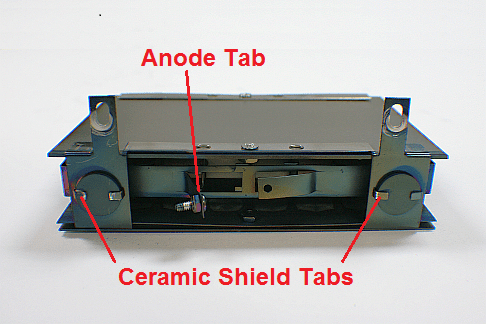
- Make sure that the filaments face out from the center post on the TSP assembly. The reason is that the filaments should warp out of position away from the filament shaft. If you face them towards the shaft then the filaments will short out and melt when they warp. See the pictures below.
- Use pliers to hold the copper coupler when tightening the filament to the shaft to prevent the shaft from bending. You need to tighten the couple quite a bit to make sure that the filament does not loosen up as the filament heats up. Note that the copper couplers get soft from use and so you may need to replace them when you change the filaments. If the coupler strips out it needs to be replaced.


RBD Instruments provides replacement titanium sublimation pump filaments, TSP flange assemblies and offers repair services for the Boostivac and TSP controllers.