A blog on the repair, operation and calibration of surface analysis systems and components including electron spectrometers, sputter ion guns and vacuum related hardware. Click on the Index tab below to see a list of all posts. Visit our website at http://www.rbdinstruments.com
The 20-327 electron gun control is used on the Physical Electronics 610 series scanning auger electron systems. The 20-327 is also a replacement for the obsolete 18-080 and 18-085 electron gun controls.
20-327 front panel
Once you have adjusted your elastic peak for best shape with max counts you will need to adjust your 20-327 R47 for proper alignment of the beam voltage calibration. Please read all of procedure before proceeding.
1) Place a piece of clean copper in your system, Run an alignment and adjust your Z axis until you get good counts with good shape. Not one or the other but both.
2) NOTE: DO NOT MOVE STAGE FROM THIS POINT ON.
3) You will not care about the position of the peak we will adjust this in the 20-327.
4) Acquire a survey and adjust the AES scale factor located in hardware properties until your copper peak is at 920 differentiated. Remember in the scale factor adjustment higher value lowers the peak and lower values raise the peak
5) Next run an alignment and see where your elastic peak is located. If peak is not at 2K move on to steps 6,7and 8.
6) Turn the gun off in the software. Turn off the 20-327 drop down the front panel of the 20-327 and extend the bottom board (if you do not have an extender it will take you longer but can be adjusted.
7) Adjust R47 located toward the back of the board located in diagram 1
8) Adjust half a turn; replace the board and power up the 20-327 and Augermap software. Run an alignment determine the direction the pot moves the peak. Adjust accordingly until your alignment is right on 2KV and then run a survey and make sure your Cu1 peak is 920 diff. If peak is not perfect run procedure (step 3 to 8 until elastic peak and Cu1 are in proper positional alignment).
This post explains the 9103 picoammeter bias modes and also explains the concept of “floating”.
There are 4 picoammeter bias modes:
No bias – the current source is connected directly to the picoammeter input
Internal – a low noise DC supply (two 45 V DC batteries in series) provides a bias between the current source and the input of the picoammeter. This application is typically used for providing a +90V bias to a target in a vacuum chamber in order to prevent secondary electrons from leaving the sample. Adding the 90V bias results in a more accurate measurement for both electron and ion current. It is also possible to use regular 9V batteries and so lower internal bias voltages are possible. Batteries are used for the internal bias as they are very clean with no ripple.
External –
There are two external bias options for the 9103, both are limited to 600 V DC.
9103EXTBIASPR has a BNC connector on the back of the 9103 that connects to the customer’s voltage source which needs to be isolated from ground (floating).
9103DBPR (shown below) has two BNC connectors on the front panel of the 9103 and the 9103 floats on the customer’s ground referenced DC voltage source.
The 9103DBPR is the most common external bias option as most voltage sources are referenced to ground (not isolated).
Two BNC connectors are used to float the 9103 up to as much as +/- 600V DC with an external low noise voltage source (provided be the user). The voltage source is connected to the HV (signal ground) BNC connector and the 9103 and the current source (DUT) is connected to the Input BNC connector.
The maximum voltage that can be applied in this mode is 600V DC (that is the rating of the BNC input on the 9103 USB picoammeter).
External Bias Dual BNC
Floating – In this mode the picoammeter signal ground is raised from near chassis ground up to a value as high as +/- 5000V DC. If you were to measure between the signal input and the signal ground reference the voltage would be low (under 1V typically). However measuring the DC voltage from the signal reference to chassis ground the voltage would be high, the floating supply value.
When floating the 9103 USB picoammeter there are some safety considerations. First of all, the input to the 9103 is changed from a BNC to either a SHV or MHV connector (user specified). These connectors are rated for up to 5kV. The recorder output on the back of the 9103 also floats. For example if you apply a floating voltage of 1000V the recorder output would also measure 1000V with respect to chassis ground. So if you are using the recorder output and also floating the 9103 the meter that you are measuring the recorder output with also needs to be isolated from ground. Finally, to prevent voltage spikes a current limit resistor is placed between the floating supply and the 9103 signal ground. The floating mode is typically used to measure the collector output of an electron multiplier or a Faraday cup.
The maximum float voltage with the latest rev 9103 is +/- 5000 V DC. If your 9103 was purchased before January 2019 then it can only float up to 1500V DC maximum.
The floating mode cannot be used with either the internal or external bias modes. However you really would not need either of those options as you can float the 9103 up to get what ever bias you need. For example, let’s say you want to measure an ion beam that is at 3000V DC and you wanted to retard the ions by 200V. You could simple set the bias supply to +3200 V DC and you would be retarding the 3000 V beam by 200V DC.
For all modes of operation the chassis ground of the 9103 USB picoammeter should be connected to the ground on the PC or chamber.
If you would like more detailed information please contact us via email at the link in the upper right hand corner of our website at www rbdinstruments dot com.
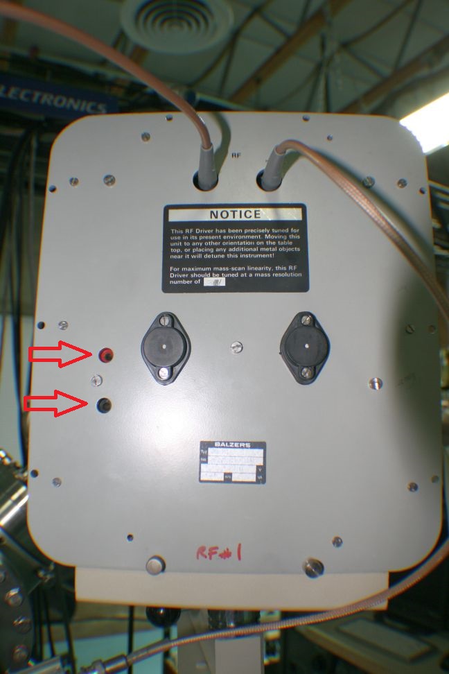
This post shows you how to calibrate the Balzers QMH RF generators that are used on the PHI SIMSII and 6300/6600 series SIMS systems.
1. Load in a Molybdenum sample. Note that the sample mount covers on PHI sample mounts are made out of Molybdenum so if you have one of those on your sample you can use the cover.
2. Monitor the voltage on the two recessed banana jacks on the front of the RF generator with a DVM set to DC millivolts.
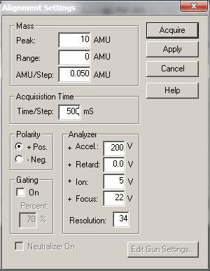
3. In AugerScan set up a SIMS alignment with a Peak AMU of 10 and a range of zero. Note that for this adjustment the ion beam does not need to be on.
4. Acquire the alignment and adjust the Tuning capacitor on the back side of the RF generator for the minimum voltage. The capacitor is a tuning type like what was used in old radios. The shaft of the capacitor is attached to a wheel with holes in it. To adjust the capacitor you put a small thin screwdriver or an Allen wrench into one of the holes and move the capacitor wheel left and right. There is a little bit of hysteresis in the adjustment so you will need to go back and forth a little bit to make sure that you are at the minimum voltage value.
The DC voltage will minimize at about 10 to 20mV depending on the RF generator AM range and the size of the quadrupole.
Once you have minimized the DC voltage stop the alignment. Change the AMU to 50 and repeat step 4.
5. Next change the AMU in the alignment to 200 AMU and adjust for minimum voltage. 200 AMU is as high as you will need to go as most of the RF generators only go up to a maximum of 250 AMU. But even if you have one that goes up to 500 or even 1000AMU, the effective signal above 200 AMU is minimal and so I think that it makes more sense to optimize the tuning over the effective range of the RF generator rather than the absolute maximum AMU. The voltage at 200 amu will be about 400 to 600mV depending RF generator AMU range and the quad diameter. The important thing is to minimize the voltage at 200 AMU.
After tuning the next step will be to adjust the peak positions.
6. The ion beam needs to be set up for normal operation and the raster turned OFF. Open the O2 leak valve on the SIMS II energy analyzer (top of SIMSII) and set it so that the vacuum in the chamber is 2 X 10⁻⁷ Torr. There is some hysteresis in the gas line so be very careful when adjusting this valve. My technique is to slowly open the valve and as soon as I see the pressure in the chamber starting to come up I close the valve ¼ turn and wait for the pressure to stabilize before further adjustment.
7. Set up an alignment in POS SIMS with an AMU of 16 and a range of 3. Set the time per step to 50ms.
8. Acquire the alignment and adjust the Cal LOW potentiometer on the RF generator so that the 16 AMU O2 peak is centered. Note that for this adjustment the ion beam needs to be on. CCW moves peak up.
9. Change the AMU to 98 and a range of 3. Adjust the Cal HIGH potentiometer on the RF generator so that the 98 AMU moly peak is centered. The 98 Moly peak will be the highest peak in the group of peaks between 92 and 100 AMU. CCW moves peak up.
10. Recheck the 16 AMU peak and readjust if necessary. If you adjust the 16 AMU peak then you will also need to adjust the 98 AMU peak as well.
Next we will adjust the resolution linearity. The resolution is adjusted by a combination of the Resolution number in the software and also the actual resolution fine potentiometer on the RF generator. We will adjust the resolution for what is called the 10% value. The 10% value represents the ratio between the 95 and 96 Moly peaks and when viewed in the log scale is one order of magnitude on the graph. We further will want to adjust the resolution linearity so that the peaks from 90 to 100 AMU and also 185 to 195 AMU on Moly are both showing approximately a 10% peak to valley ratio, as shown in the survey below.
The resolution number in the software acts like a resolution offset – it affects the entire range of AMU. The resolution gain potentiometer on the RF generator acts like a gain, it has more effect on the high AMU than the low AMU. By selecting the correct Resolution number in the software and adjusting the resolution Fine potentiometer on the RF generator the overall resolution linearity can be adjusted.
11. Set up two survey windows in AugerScan. One will be set from 90 to 100 AMU and the other from 185 to 195 AMU. Initially set the resolution in the software to the last known good value or the value that is written on the front of the RF generator. Use an AMU of .05 and a time per step of 50 ms, one sweep.
12. Acquire both surveys (one at a time).
In each window the goal is to have approximately 10% peak to valley ratio (in the log scale). Adjust the resolution number for the 90 to 100 AMU peaks and the resolution fine for the 185 to 195 peaks. CW = more resolution. Remember that the Resolution number in the software will affect both the low and high peaks, and that the resolution fine pot on the RF generator will have more effect on the high peaks than the low peaks. Here is a table that might be helpful-
Note that any time you change the resolution number for the 90 to 100 survey you need to change it to the same value for the 185 to 195 survey.
After a few iterations you will have the resolution set so that both the low and high AMUs are approximately 10% resolution.
13. Once the resolution linearity adjustment is complete, recheck the 16 AMU and 98 AMU peak positions and adjust if necessary.
If you run out of range on the resolution fine adjustment or the cal low peak position contact RBD Instruments for additional procedures on how to correct those issues.