Homemade Titanium Sublimation Pump

In this post I show how we made a small homemade titanium sublimation pump for an 8” Kimball Physics spherical octagon UHV vacuum chamber.

Our little chamber has a 60 l/s ion pump, but even with baking (both IR and UVC), we were able to get only into the low 10-8 to high 10-9 Torr range.  However, using the little titanium sublimation pump, which we “Frankensteined” together using parts we had readily available, allowed us to get in the low 10-9 to high 10-10 Torr range, a factor of ten improvement.

A titanium sublimation pump works by heating a titanium filament wire to about 1300 degrees C. That is hot enough to create titanium gas molecules (sublimate) but not so hot that the filament wire melts.  The sublimated titanium deposits on the wall of the chamber (or preferably on a shield wall) and forms a thin film. This layer of titanium is very reactive and will bond with other molecules in the vacuum chamber such as CO and O2. Disassociated hydrogen and water vapor also diffuse into the titanium layer.

The reactivity of the titanium film is increased with lower temperatures, but most titanium sublimation pumps are operated at room temperature. Over time, the titanium film will become coated and need to be replenished. All commercial titanium sublimation pumps have 3 to 4 filaments so that when one filament burns out you can switch to another. Those filaments are also relatively thick in diameter at 12 gauge (.080”) and need about 50 amps of current to operate.

For our homemade titanium sublimation pump, we used 24 gauge (.020”) so that we could operate at a much lower current of 4 amps.  We also only have one filament.

Before I show how we made our homemade titanium sublimation pump, here are links to some videos on how TSPs work:

https://www.youtube.com/watch?v=j5Y7m2ZJfgg

https://www.youtube.com/watch?v=9vJedaxRsxI

The first thing that we needed was a 2-pin electrical feedthrough on a 2.75” CF flange.  For that we used a Getter pump flange from a PHI 04-303 ion gun as shown below.

filament_wire_connections

filament_wire_connections

We then needed to somehow support and electrically isolate the TSP filament wire. To do that we used a coupler and some little shoulder washers.

Ceramic_support

Ceramic_support

The top part of the getter pump assembly is conveniently designed to allow gas molecules to pass through but also block direct deposition of titanium into the vacuum chamber.

blocks_direct_deposition

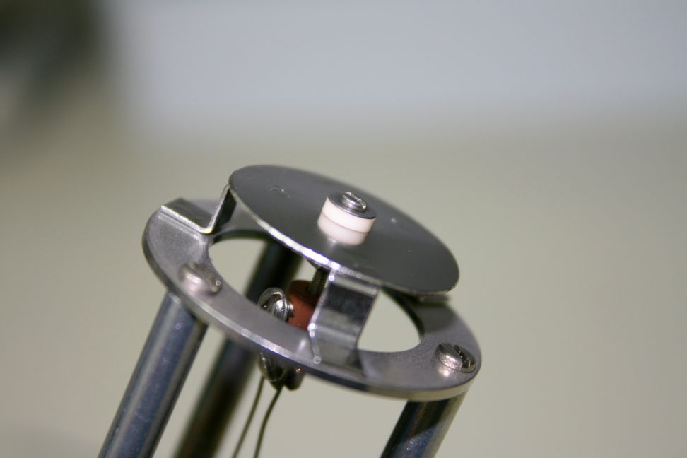
Next we added a few turns into the titanium wire so that it would have a little bit of a spring to it. Then we connected the wire to the flange and support assembly. We have only one filament and so by effectively doubling the length of the wire we could also double the amount of titanium that we would be sublimating.

filament_wire

filament_wire

For a chamber wall we used a 2.75” nipple that has a tube ID of 1.6” and a length of 4”.  The larger the surface area the better, but for the size chamber that we have, we are limited to a small 2.75” nipple. We mounted this nipple on our chamber horizontally so that any flakes that form will not get into the chamber or ion pump.

2.75_inch_CF_nipple

2.75_inch_CF_nipple

For a power supply, we used a 30 volt 5 amp Lavolta.

30V_5amp_power_supply

30V_5amp_power_supply

After installing our homemade titanium sublimation pump into the chamber we pumped down and were ready to operate the TSP.

To operate our titanium sublimation pump, we slowly increased the power supply current while observing the color of the light coming off the TSP filament and also monitoring the chamber pressure.  The filament needs to be orange for the titanium to sublimate. Too hot and the lifetime of the filament will be reduced. Too low and the pumping effect is reduced. By experimenting we determined that about 3.8 amps DC was the correct amount of current.  Once that was determined, we could just periodically turn the TSP on for about 2 minutes at a time.  We did that 3 times over a 6-hour period and then let the chamber pump overnight. The next morning we were in the high 10-10 Torr range.  Success!

tsp_filament_in_operation

tsp_filament_in_operation

Conclusions:

  1. It is possible to make a small titanium sublimation pump using off-the-shelf components that will operate with less than 5 amps of DC current.
  2. Adding a titanium sublimation pump to a small chamber can help to get from HV to UHV.


Resolving USB Conflicts with Virtual COM Ports

If you run multiple USB devices that operate as virtual RS232 COM ports (the ubiquitous serial port standard) on Windows, you may have run into problems with conflicts between devices. An application may connect to the appropriate device when it’s the only one connected, only to “get confused” if there is another device sharing the PC. Happily, there are a few simple things you can try that will often resolve the problem.

9103s and Arduinos Playing Nice Together

9103 and Arduino USB Devices

A 9103 Picoammeter and Arduino

To most Windows applications, virtual COM ports (VCPs) all look the same. An application can open a port and and attempt to communicate with the connected device, but since there’s no fixed protocol – each device speaks its own “language”, any message sent can have undetermined effects if the device you’re communicating with is not the one your were expecting. Some applications simply connect to the first COM port available, other’s may provide a way to select the COM port your device is connected to – but you’re still responsible for figuring that out.

When manufacturers produce hardware for PCs they can apply for unique vendor ad product IDs for their device, and there are ways for applications to safely query these. But that only solves part of the problem. Many devices use third-party USB chips and drivers from companies like FTDI, so they share the same IDs. These devices look the same to a Windows client application, or to a person perusing the Device Manager in Control Panel.

RBD’s own 9103 Picoammeter utilizes FTDI’s popular USB VCP chips, as do many versions of the popular Arduino microcontroller boards, so these two sets of devices can be confused by client applications when used on the same PC. And s it turns out, they are often used together. Here are a few tricks for getting these device to play nice together.

Solution 1: Connect Each Device and Run Each Client in Order

Many applications require you to specify the port for the selected device. Others (like Actuel for the 9103) poll the COM ports in numerical order and check and connect to the first available. If these devices first check the vendor and product ID (like the 9103), they will at least skip ports that do not match. But they cannot distinguish between two devices using the same USB chip (like FTDI’s). Setting up a device connection / application order can solve this.

In the case of a 9103 / Arduino conflict, remove all other devices, then plug in the 9103 and power it on. Next run the Actuel software. The software will find and take control of the 9103 port, and once assigned, you can safely plug in the next device and run its client.

Another order might make more sense for your particular application. Experiment with your configuration, and there are more than two devices, try getting two working first. Document the process and just make sure it’s followed anytime you reboot / power-on.

Solution 2: Change the COM Port Number for a Particular USB Port

You can force Windows to use a different COM port number than the one automatically assigned. This may help with applications that select the lowest numbered port.

For example, if the 9103 is connected to COM4 and another FTDI device is on COM3, the 9103 client software may incorrectly select the device on COM3. Setting the 9103 to COM2 may allow you to now connect the devices and run the client applications in any order, depending on how those other devices / applications behave. Some experimentation may be necessary.

With the 9103 connected and turned on, run Control Panel / Device Manager, and find the selection for “Ports (COM and LPT)”, click and you should see an entry for “USB Serial Port (COM4)” (the COM# may be different of course). Double-click for properties.

The COM port settings for the 9103 USB VCP

The COM port settings for the 9103

Now select the “Port Settings” tab, and click the “Advanced…” button. From this window you can select a new COM port assignment:

Choosing a COM port for the 9103

Choosing a COM port for the 9103

Keep in mind that plugging a device into different USB port will change the COM port assigned to it.

More Info

Of course, you’ll want to ensure you have the latest drivers installed. For FTDI, they can be found here:

http://www.ftdichip.com/FTDrivers.htm

If you’re thinking of programming your own serial port application, here’s a quick tutorial at the API level. Many popular languages include code for VCP programming, and third-party libraries are available:

http://xanthium.in/Serial-Port-Programming-using-Win32-API

Loading PHI specimen mounts

Loading PHI specimen mounts

This post explains the mechanics involved with loading PHI specimen mounts used on most of the older to current Physical Electronics surface analysis systems.

There are a number of different sizes and shapes of specimen (sample) mounts and they all use the same basic mounting and docking scheme.

The most common sample mount used on older Physical Electronics XPS and AES surface analysis systems is the Model 190 flat one inch diameter specimen holder shown below.

Model 190 sample mount

Model 190 sample mount

The basic concept is that there are two grooves on the outside of the sample mounts which are used to transfer the sample mount into the vacuum chamber, and to dock the sample mount to the specimen stage. The transfer arm has a fork on the end which connects to the bottom groove on the specimen mount and the specimen stage has three clips which snap into the bottom groove and hold the specimen mount to the stage.   The top groove is used to hold the specimen mount while mounting it to the transfer arm fork or in the case of scanning auger systems, to transfer to the parking attachment.

one_inch_sample_mount_from_side

Grooves on 190 specimen mount

Clips on specimen stage

Clips on specimen stage

There are two essential steps required to successfully dock and removing the specimen holders;

  1. Make sure that the specimen stage is perfectly centered under the transfer arm fork.
  2. The specimen stage center clip needs to be lined up with the notch on the transfer arm fork.
Line up intro fork notch to clip

Line up intro fork notch to clip

line up sample over specimen stage

line up sample over specimen stage

Once you have the location of the specimen stage micrometers for the load and un-load positions you can make some marks on the specimen stage micrometers so that you will be able to easily re-position the specimen stage for loading and unloading.

 Loading PHI sample mounts procedure:

  1. After you attach the sample that you want to analyze to the specimen holder (using screws and clips or carbon/silver tape). Back-fill the intro with dry nitrogen and mount the specimen holder to the sample fork. There are 2 different types of specimen mount holding tools as shown below. Or you can use a clean needle nose pliers. Pull the transfer arm out a little bit so that you can lower the specimen mount into the load lock and then move the transfer arm back in so that the fork slides over the bottom groove on the specimen mount.
    specimen mount  holding tool

    specimen mount holding tool

    sample holding tool

    sample holding tool

  2. Pump down the load lock by pressing the Pump Intro button on the AVC remote box.
  3. Move the specimen stage micrometers to the load sample position. The X and Y axis will be centered under the intro fork but the Z axis will be lowered from the dock position by at least 1 cm.
  4. After the load lock has pumped down (5 bars on the AVC remote plus a few more minutes – the longer you pump the sample, the lower the pressure burst and the less out-gassing you will have) press the  Intro Sample button on the AVC remote and the V1 gate valve will open.
  5. Move the intro arm forward to bring the sample into the vacuum chamber and push it all the way in until it hits the stop. If adjusted properly, the stop will be the correct position for docking the specimen mount.
  6. The specimen mount should be directly above the specimen stage clips.  If not adjust the X and Y on the specimen stage as needed.

    one_inch_sample_puck_above_specimen_stage

    one_inch_sample_puck_above_specimen_stage

  7. Raise the specimen stage Z axis so that the clips slide into the specimen holder bottom groove. You may need to slightly adjust the X Y or rotation (if so equipped) so that the specimen holder snaps into the clips.   Slightly moving the specimen stage rotation or the tilt on the transfer arm can also help the specimen mount to snap down into the clips on the specimen stage as you move the specimen stage Z axis.   If the specimen mount does not snap down with a minimal amount of force, back off and recheck the specimen stage X and Y position.  You do not want to damage any of the three clips on the specimen stage by crushing them. Once the clips have snapped in adjust the Z slightly until there is no gap between the bottom of the specimen holder and the specimen stage.

    one_inch_sample_puck_docking

    one_inch_sample_puck_docking

  8. After the specimen mount is docked to the specimen stage, slowly retract the intro fork until it separates from the specimen holder and then once clear, pull the intro arm all the way out of the chamber. The V1 gate valve will close automatically.

To remove a sample from the system, repeat the above procedure with the exception that the Z axis should be in the dock position so that the intro arm fork mounts to the lower groove of the specimen mount. Once you dock the load lock fork to the specimen mount, drop the Z axis on the specimen stage in order to separate the specimen holder from the specimen stage clips.

When the specimen holder is clear of the specimen stage you can pull the intro arm all the way out of the chamber and V1 will close automatically.

RBD Instruments provides new and used PHI specimen mounts.  We also provide the sample clip assembly. Contact us for more information.

RBD specimen mount part numbers

RBD specimen mount part numbers

This slideshow requires JavaScript.