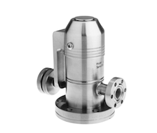
The CF flange (also commonly referred to as the Varian trade-marked Conflat) uses a knife edge that cuts into a soft metal gasket (usually copper) to provide a leak-tight metal-to-metal seal. “Protect the knife edge at all costs” is a common catchphrase at RBD Instruments that we like to drill into anyone who works on a UHV vacuum chamber. Simply put, it means to use care when removing used copper gaskets from Conflat (CF) flanges, and to protect the flange edge with aluminum foil when it is being stored on a shelf. Even a small scratch on the knife edge can result in a leaky seal on the flange.
Specialized tools are available for removing copper gaskets, but most labs do not have them. So, what is the best way to remove a copper gasket from a CF flange if you do not have a special tool? IMO you should use a clean regular channel lock or vice grip type of pliers whenever possible to remove used copper gaskets instead of a flat blade screwdriver. You need to use pliers that have teeth, not the smooth ones. In some cases you will not be able to use pliers as there is not enough room to get the pliers onto the gasket without risking damage to a ceramic or some other optic part. In those cases, you will need to use a straight blade screwdriver.
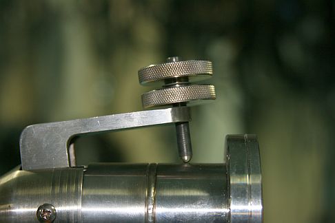
To use pliers, you simply position the jaws of the pliers on the inner and outer diameters of the gasket and tilt the pliers back. The applied leverage will pop the gasket out of the groove. Be sure to get a good grip on the edge of the gasket as quite often the gasket is pressed in very tightly and will be somewhat difficult to remove. Other times the gaskets will practically fall out by themselves. It just depends on the fit of the flanges and whether or not the system has been baked out (the copper expands during bake-out).
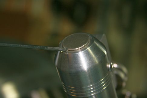
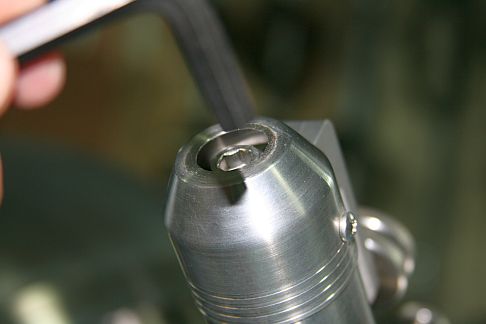
When using a screwdriver, extreme care must be taken to ensure that the screwdriver does not slip off the side of the gasket and damage the knife edge once the gasket pops out of the flange recess. You can reduce the chances of damage by using a screwdriver that has a tip that is flat with sharp edges and slightly thinner than the height of the exposed gasket edge. Apply downward pressure on the tip of the screwdriver as you try to pry the gasket up. Sometimes the gaskets can be wedged in very tightly after compression and be difficult to remove. Use the tip of the screwdriver to leverage the gasket out; do not push the screwdriver. This is when one is most likely to damage a knife edge: if the screwdriver slips as the gasket comes loose, it may scrape across the knife edge and cause a large scratch or gouge. Once that happens, the flange may no longer seal properly.
If you do gouge a knife edge you might be able to still get it to seal by using a small piece of a soft vacuum-compatible metal such as gold or platinum to fill in the void on the gouge. Small scratches can be polished out with some ultra-fine emery cloth. If the gouge is too big then the flange may need to have the knife edge touched-up with a metal lathe. That is not always practical or even possible. So, the best thing to do is to… protect the knife edge at all costs.
When flanges are being stored for long periods of time or are being stacked up on a shelf, the best way to protect them is to wrap them in UHV aluminum foil. You can purchase UHV compatible aluminum foil from All-Foils Inc. http://www.allfoils.com/single-product/uhv-foil/
Below are some pictures of the correct and incorrect techniques to remove copper gaskets from CF flanges. If you need to purchase some copper gaskets for your UHV vacuum chamber and also want to pay the lowest possible price, RBD Instruments Inc. now provides copper gaskets for CF flanges in small or large quantities at low prices. Click on this link for more information // Copper gaskets for CF flanges // or visit us at our website by going to RBD Instruments dot com.
-

- Grip edges of copper gasket
-
- Tilt pliers back
-
- Remove the gasket
-
- Incorrect way to remove copper gasket from CF knife flange
-
- Press screwdriver against edge of copper gasket on CF flange
-
- Twist screwdriver to remove copper gasket from CF flange
-
- Use screwdriver to remove a copper gasket on a CF flange
-
- Do not push the screwdriver
-
- Damaged CF flange knife edge