A blog on the repair, operation and calibration of surface analysis systems and components including electron spectrometers, sputter ion guns and vacuum related hardware. Click on the Index tab below to see a list of all posts. Visit our website at http://www.rbdinstruments.com
Category Archives: General Optics and Vacuum
General information on repair, maintenance, and operation of both PHI (Physical Electronics) and other manufacturers’ systems and components
An easy way to determine whether or not an ion pump needs to be rebuilt is to perform an endoscopic ion pump inspection. The hard way is to drop the ion pumps.
In the last few years the prices have really come down on USB and android/iPhone endoscopes. If you do a search on EBay for USB endoscope you will see a lot of choices for under $20.00. The one used in this blog post is 7mm in diameter, which is small enough to fit into a 1.33” CF flange hole.
endoscope
endoscope_for_phone
For this example we inspected a PHI 660 scanning auger system equipped with a 220 l/s ion pump. This system has been in use for about 10 years primarily for depth profiling using Argon gas.
Since there is a shield below the TSP filaments the only way into the ion pumps was thru the un-used 1.33 CF flange that is opposite the ion pump high voltage connector.
The color corrected pictures below show that the ion pump elements are pitted, the insulating ceramics are coated and there are some flakes in the bottom of the pump well. The conclusion was that the pump elements have another year or so left on them and so we will plan on replacing them in 12 to 18 months.
This post shows you how to calibrate the Balzers QMH RF generators that are used on the PHI SIMSII and 6300/6600 series SIMS systems.
1. Load in a Molybdenum sample. Note that the sample mount covers on PHI sample mounts are made out of Molybdenum so if you have one of those on your sample you can use the cover.
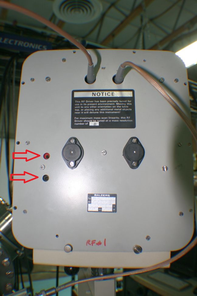
2. Monitor the voltage on the two recessed banana jacks on the front of the RF generator with a DVM set to DC millivolts.
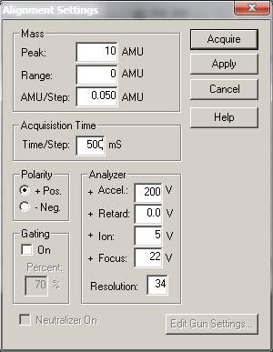
3. In AugerScan set up a SIMS alignment with a Peak AMU of 10 and a range of zero. Note that for this adjustment the ion beam does not need to be on.
4. Acquire the alignment and adjust the Tuning capacitor on the back side of the RF generator for the minimum voltage. The capacitor is a tuning type like what was used in old radios. The shaft of the capacitor is attached to a wheel with holes in it. To adjust the capacitor you put a small thin screwdriver or an Allen wrench into one of the holes and move the capacitor wheel left and right. There is a little bit of hysteresis in the adjustment so you will need to go back and forth a little bit to make sure that you are at the minimum voltage value.
The DC voltage will minimize at about 10 to 20mV depending on the RF generator AM range and the size of the quadrupole.
Once you have minimized the DC voltage stop the alignment. Change the AMU to 50 and repeat step 4.
5. Next change the AMU in the alignment to 200 AMU and adjust for minimum voltage. 200 AMU is as high as you will need to go as most of the RF generators only go up to a maximum of 250 AMU. But even if you have one that goes up to 500 or even 1000AMU, the effective signal above 200 AMU is minimal and so I think that it makes more sense to optimize the tuning over the effective range of the RF generator rather than the absolute maximum AMU. The voltage at 200 amu will be about 400 to 600mV depending RF generator AMU range and the quad diameter. The important thing is to minimize the voltage at 200 AMU.
After tuning the next step will be to adjust the peak positions.
6. The ion beam needs to be set up for normal operation and the raster turned OFF. Open the O2 leak valve on the SIMS II energy analyzer (top of SIMSII) and set it so that the vacuum in the chamber is 2 X 10⁻⁷ Torr. There is some hysteresis in the gas line so be very careful when adjusting this valve. My technique is to slowly open the valve and as soon as I see the pressure in the chamber starting to come up I close the valve ¼ turn and wait for the pressure to stabilize before further adjustment.
7. Set up an alignment in POS SIMS with an AMU of 16 and a range of 3. Set the time per step to 50ms.
8. Acquire the alignment and adjust the Cal LOW potentiometer on the RF generator so that the 16 AMU O2 peak is centered. Note that for this adjustment the ion beam needs to be on. CCW moves peak up.
9. Change the AMU to 98 and a range of 3. Adjust the Cal HIGH potentiometer on the RF generator so that the 98 AMU moly peak is centered. The 98 Moly peak will be the highest peak in the group of peaks between 92 and 100 AMU. CCW moves peak up.
10. Recheck the 16 AMU peak and readjust if necessary. If you adjust the 16 AMU peak then you will also need to adjust the 98 AMU peak as well.
Next we will adjust the resolution linearity. The resolution is adjusted by a combination of the Resolution number in the software and also the actual resolution fine potentiometer on the RF generator. We will adjust the resolution for what is called the 10% value. The 10% value represents the ratio between the 95 and 96 Moly peaks and when viewed in the log scale is one order of magnitude on the graph. We further will want to adjust the resolution linearity so that the peaks from 90 to 100 AMU and also 185 to 195 AMU on Moly are both showing approximately a 10% peak to valley ratio, as shown in the survey below.
The resolution number in the software acts like a resolution offset – it affects the entire range of AMU. The resolution gain potentiometer on the RF generator acts like a gain, it has more effect on the high AMU than the low AMU. By selecting the correct Resolution number in the software and adjusting the resolution Fine potentiometer on the RF generator the overall resolution linearity can be adjusted.
11. Set up two survey windows in AugerScan. One will be set from 90 to 100 AMU and the other from 185 to 195 AMU. Initially set the resolution in the software to the last known good value or the value that is written on the front of the RF generator. Use an AMU of .05 and a time per step of 50 ms, one sweep.
12. Acquire both surveys (one at a time).
In each window the goal is to have approximately 10% peak to valley ratio (in the log scale). Adjust the resolution number for the 90 to 100 AMU peaks and the resolution fine for the 185 to 195 peaks. CW = more resolution. Remember that the Resolution number in the software will affect both the low and high peaks, and that the resolution fine pot on the RF generator will have more effect on the high peaks than the low peaks. Here is a table that might be helpful-
Note that any time you change the resolution number for the 90 to 100 survey you need to change it to the same value for the 185 to 195 survey.
After a few iterations you will have the resolution set so that both the low and high AMUs are approximately 10% resolution.
13. Once the resolution linearity adjustment is complete, recheck the 16 AMU and 98 AMU peak positions and adjust if necessary.
If you run out of range on the resolution fine adjustment or the cal low peak position contact RBD Instruments for additional procedures on how to correct those issues.
When it comes to locating vacuum chamber leaks, there are a few different methods that can be used depending on the vacuum level of the leak.
I like to categorize leaks into three types- Gross leaks, mid vacuum leaks and high vacuum leaks.
Gross leaks are the type where the chamber will only pump down somewhere between atmosphere and the low 10-2 Torr range. With this type of leak the vacuum is not good enough for an ion gauge to turn on.
The first thing that you want to do with any leak is to make sure that all the flanges you worked on have been tightened correctly and appear uniform. If a flange has a wider gasket gap on one side than the other, then that flange may not be seated properly.
Next you will want to make sure that your pump (usually a turbo pump) can reach vacuum when not pumping on the vacuum chamber. Then while monitoring the vacuum on your turbo pump or rough pump with a TC gauge, squirt some isopropanol or methanol on suspected flanges while watching the vacuum gauge. Typically the vacuum will come down (pressure will go up) when the isopropanol or methanol finds its way into the leak. Then vent and replace the suspect gasket.
The other technique useful for gross leaks is to slightly pressurize the system with nitrogen and then squirt the suspected flanges with Snoop (or soapy water). For most vacuum chambers you do not want to pressurize them with more than 3 PSI. The reason that you do not over pressurize a vacuum chamber is because viewports are slightly concave and designed to hold vacuum, but not designed to hold pressure. Over pressurizing a vacuum chamber can cause the viewports to blow out – not good and also a safety hazard. When you find the leak, you will see bubbles forming.
For mid vacuum leaks, the ion gauge will function and the vacuum will be somewhere between the low 10-3 Torr and the high 10-8 Torr range. For this type of vacuum leak, monitor the ion gauge while squirting some isopropanol or methanol onto the suspected flanges. In this vacuum range when the isopropanol or methanol makes its way into the leak, the vacuum may improve or degrade, but you will see a definite change in the vacuum. Sometimes the isopropanol or methanol will plug up the leak momentarily and the vacuum will improve noticeably. You can use a heat gun to evaporate the isopropanol or methanol on the flange where you noticed the vacuum change. Then after the flange cools down, repeat the procedure to confirm the location of the leak.
For high vacuum leaks in the low 10-8 Torr to the low 10-9 Torr range, squirting the flange with isopropanol or methanol usually will not work. In those cases, you may need to use an RGA (residual gas analyzer) to find the leak. To use an RGA you would need to vent the chamber and install an RGA on one of the flanges, then pump back down and possibly even bake the chamber out depending on the level of the leak. For example, if the leak is in the low 10-9 Torr then you will probably need to bake out the chamber in order to get down that low.
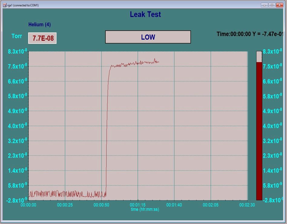
Once you are back to your base vacuum you would set up the RGA in the leak check mode or just scan over the 4 AMU helium peak. Then using helium that is connected through a regulator to a small tube, bleed a small amount of helium over the suspected flanges and feedthroughs while monitoring the helium peak on the RGA. Helium is a very small molecule and so it will pass into the leak and then be detected by the RGA. For best results I have found that you need to close off your pumps (or turn off your ion pump) while leak checking with helium. Just keep an eye on your vacuum and make sure that you pump out the chamber periodically to keep the vacuum at least in the 10-6 Torr or better. When you find the leak with helium you will see an immediate and dramatic change in the RGA scan (as shown below). It will be easy to confirm the location of the leak by pumping out the helium and then repeating the experiment.
RGA Leak test Helium
For large industrial vacuum chambers portable leak checkers are available so that the chamber does not need to be vented to install the RGA.
What happens if you can’t find a leak? In the case of high vacuum leaks if you can’t find a leak, there may not be a leak. Sometimes what appears to be a leak is really just a whole lot of water vapor, a virtual leak or possibly hydrocarbon contamination. In these cases, a very long bake out should solve the problem. Long as in 24 or 36 hours at 150 to 200 degrees Celsius.
RGAs start at about $3,500.00 and go up from there depending on Mass range, multiplier and energy filter options. Here are some links to RGA companies –
Once you do find the leak you may need to remove water vapor from the chamber in order to obtain a better base vacuum. A number of water vapor desorption options are available from RBD Instruments at this link – Water Vapor Desorption