A blog on the repair, operation and calibration of surface analysis systems and components including electron spectrometers, sputter ion guns and vacuum related hardware. Click on the Index tab below to see a list of all posts. Visit our website at http://www.rbdinstruments.com
This 11-155 Voltage Testing PDF shows the test points to measure the voltages in the 11-155 power supply which is used on the older PHI 595 and 600 scanning auger systems.
Procedure:
Slide the 11-155 power supply out so that the front of the unit is resting on the floor, and the back of the unit is still in the rack. Remove the top cover.
Turn on the RBD110 main power and measure the voltages as shown in the above drawing. The 5 volt supply usually is between 5 and 5.4 volts DC. The plus and minis 20 volts supplies are usually between 19.5 and 20.5 volts DC. All supplies should have less than 10 mV AC ripple.
If you have a bad 20V or 5V power supply, RBD Instruments has replacement units in stock.
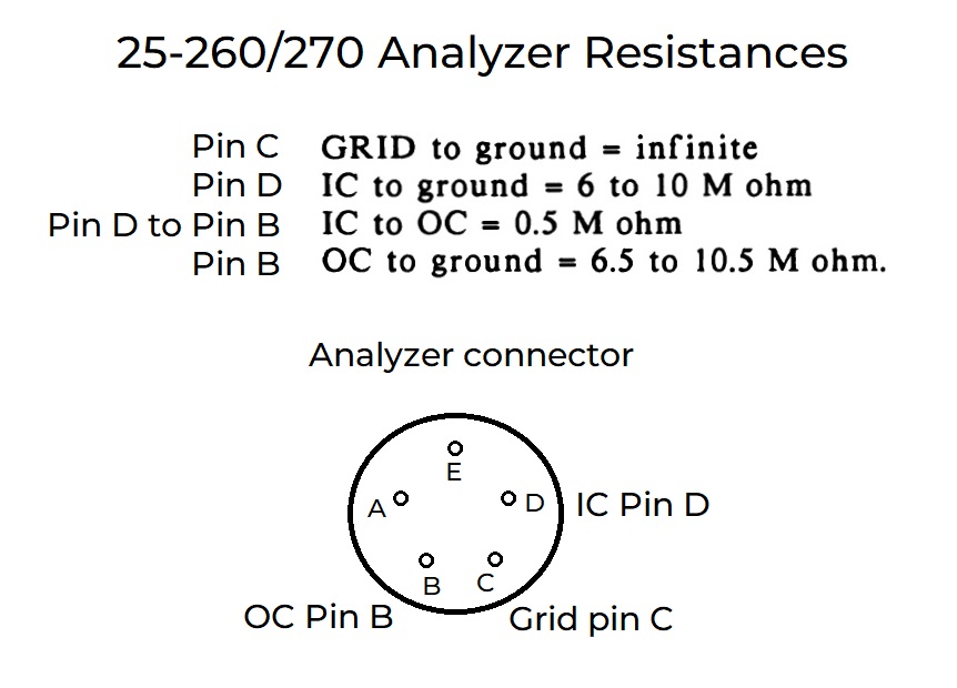
This procedure details the step by step process to replace the tungsten filament in a PHI 25-250, 260 or 270 ESCA analyzer used on the older PHI 550, 560 and 570 ESCA systems. RBD Instruments provides this filament (the C75-010).
Here are the pin outs and resistances on the analyzer connector –
Overview:
By following this procedure you will be able to safely replace the filament assembly in your PHI 25-270 or 25-260 double pass ESCA/Auger CMA. These analyzers are used in the PHI 570 and 560 ESCA/Auger systems, respectively.
Safety Warning: This analyzer is heavy. Be careful when removing and installing the analyzer from the system. Do not attempt to remove the analyzer unless you are capable of lifting 70 lbs.
Tools required:
Small straight screwdrivers
Tweezers
Long needle nose pliers
Bristol wrench
Analyzer stand
De-gaussing coil
Aluminum foil (and a clean work area)
Clean gloves
Ethanol or methanol
Kimwipes or lintfree clothes
Canned air or dry nitrogen
Procedure:
Prior to beginning this procedure, clean all tools with methanol and de-gauss them. Prepare a work area and lay down some aluminum foil to place analyzer parts on. Set up the analyzer stand next to the aluminum foil. Dust off all parts as you re-assemble the analyzer.
Vent the system and remove the analyzer, carefully lifting it by the handles. Try not to touch the inside of the chamber as you remove the analyzer. Set the analyzer on the stand. If no stand is available, you can use manuals stacked up on either side of the handles to support the analyzer. A stand is highly recommended.
Remove the screw that connects the grounding wire to the magnetic shield and the grid assembly, and the grounding wire to the gun cap, if there is one.
Remove the screws around the sides of the magnetic shield and carefully lift the magnetic shield up and off of the analyzer.
Next remove the guard ring ceramic screw and set it on the foil.
Loosen the four flat head screws in the base of the guard ring assembly. These screws are located in the base of the assembly. You can see them if you look down into the four holes in the top of the guard ring assembly. Do not remove these screws, only loosen them up.
Carefully lift up the guard ring assembly and set it on the foil.
Loosen the four flat head screws on the perimeter of the aluminum conical ceramic support ring.
Carefully remove the aluminum conical ceramic support ring and place it on the table. You will need to slide the guard ring ceramic through the support ring as you lift it up.
Use a small piece of aluminum foil to connect the guard ring ceramic to the long aluminum rod that is next to it. This will prevent the guard ring ceramic from falling over and breaking.
Very carefully, lift up the conical ceramic and place it on the table. This is a very brittle and expensive part, so use extreme care when handling.
Remove the upper outer cylinder. Sometimes this part may be stuck. If so you may be able to loosen it up using a heat gun around the base. The next trick would be to use some methanol to help loosen it up. Only as a last resort, use some small straight screw driver tips to loosen it up. If you do have to use some screwdrivers, you will need to file down any nicks that you may create before this part is put back on later in the procedure.
Remove the four pan head screws at the base of the upper inner cylinder. Use extreme care not to put a hole into the grids.
Carefully work the upper inner cylinder cap up and off of the inner cylinder. Touch only the metal areas between the grids and the base. Do not touch the grids.
Set the upper inner cylinder grid cap on the table.
Loosen and remove the 4 pan head screws on the top of the gun assembly, located inside of the inner cylinder. Also tighten up the 4 flat head screws that are visible through the holes in the cooper ring.
Remove the copper ring and set it on the table.
Remove the 4 pan head screws on the upper part of the inner cylinder.
Remove the four pan head screws at the base of the inner cylinder.
Carefully lift up the inner cylinder and set it on the table. Use the same tricks as before if it is stuck. Do not touch the grids.
Loosen the four flat head screws on the aluminum support posts.
Remove the two connectors from the filament. These are the two posts at the base of the gun assembly. The connectors will slide off using a needle nose pliers.
Separate the wire that connects the emission cap to the emission wire ceramic. All of these wires are connected by a male and female pin type connector. Use a needle nose pliers and a tweezers to gently separate these types of connections.
Remove one or two of the aluminum support rods and tilt the gun assembly out so that you can loosen the spline screws on the base of the filament assembly. Be careful to keep an eye on all of the wire connections are some of them may pull loose as you tip the gun. That is OK, just make sure that you can keep track of where they were so that you can re-connect them after tilting the gun back down.
Remove the filament assembly and install the new filament assembly. You will need a spline wrench for this step. If you have only the C75-010 filament, it will need to be installed into the existing emission cap. Make sure that the new filament is well centered.
The filament is now installed, and the process will be reversed to put the analyzer back together.
After installing the filament, replace the aluminum support rods and tip the gun back on the supports. Re-connect any wires that may have come loose.
Re-connect the two filament connectors. Make sure that they are tight. If necessary, compress the connectors with a needle-nose pliers before sliding the connectors on to the filament posts.
Periodically, de-gauss the analyzer. To do this, plug in the coil and turn it on. Place it over the analyzer and move it in a circular motion around and up and down the analyzer. Slowly raise the coil up and away from the analyzer. Turn the coil 90 degrees so that it is perpendicular before turning the coil off.
Slide the inner cylinder back on top of the gun assembly. Line up the metal between the grids with the ceramics on the base of the gun assembly. The idea is to minimize any loss of signal as the electrons pass through the grids.
Re-install and tighten the four pan heads screws at the base of the inner cylinder.
Place the copper ring back on top of the inner cylinder. Line up the large holes in the copper ring with the flat head screws on the top of the gun assembly.
Replace the 4 pan head screws into the copper ring. Loosen the four flat head screws and then evenly tighten up the four pan head screws. This will pull up the gun assembly so that it is perpendicular to the inner cylinder. Make sure that the flat head screws are loose while you do this. After the four pan head screws are tight, also tighten the four flat head screws. The flat head screws are only used to support the gun assembly during the filament change. The gun assembly is secured to the inner cylinder by the pan head screws.
Replace the four pan head screws on the outer part of the inner cylinder.
Carefully replace the upper inner cylinder grid cap. Do not touch the grids. The grid opening should match with the grid openings in the lower part of the inner cylinder.
Degauss the analyzer as before.
Replace the upper out cylinder. Press it down gently but firmly to ensure that it is as far down as possible.
Very carefully, replace the conical ceramic. It should fit snuggly over the inner cylinder. Do not force it.
Replace the aluminum conical ceramic retainer ring, slide the guard ring ceramic into the hole carefully and place it on top of the conical ceramic.
Loosely tighten the four flat head screws in the ring. You will need to adjust the position of the ring (left and right) a little bit to make sure that the magnetic shield is lined up before you do the final tightening.
Replace the guard ring assembly. Line up the tab that will connect the guard ring ceramic to get the proper position. The four small flat head screws will line up with the holes in the top of the inner cylinder cap. Make sure that the assembly is flat, then tighten the four small flat head screws.
If your analyzer has a ground wire from the top of the grid assembly to the nose of the electron gun, replace that wire at this time.
Connect the guard ring wire and de-gauss the analyzer. Also remove the foil that was holding the guard ring ceramic to the aluminum post.
Slide the magnetic shield over the analyzer and check if all of the holes line up for the magnetic shield screws. There are 4 screws on the top and four larger screws on the bottom. Rotate the conical ceramic ring as needed, then tighten up the four flat head screws on the aluminum conical ceramic support ring.
Slide the magnetic shield back on and tighten all of the magnetic shield screws. Reconnect the grounding wire from the outside of the shield to the top of the grid assembly.
Congratulations! You have successfully completed a filament change on this analyzer!
This procedure is written for the PHI 660 scanning Auger system but also works for the 600 scanning Auger systems as well.
Ion pumps must be on and the system vacuum should be in the mid to low 10-7 range (or better)..
Make sure that the card rack power supply is OFF. Also make sure that these units are OFF:
20-610 High Voltage Supply
20-622 Gun control
11-065 Ion gun supply
Balzers Thermo Valve Control (gas valve also needs to be closed)
The DIGIII ion gauge control and Boostivac ion pump control should be ON.
Remove all cables that are above the table top. These include the Auger analyzer, SIMS analyzer (if so equipped), 96A V/F preamp, 1182 or 1120 amplifier discriminator, and the 97 SED preamp. TIP: Make sure that the cables are labeled as you remove them.
When removing the 97 SED preamp be careful not break the feedthrough pins! Also when you put it back on after the bake-out make sure it is flush with the flange and then use a flat blade screwdriver to tighten the screws – snug plus 1/8 to 1/4 turn.
Remove the filament cap on the top of the analyzer (3 screws at the base, do not unscrew the cable!).
All of the cables above the table top should now be removed.
Remove the wooden tabletops.
Pull up on the table top switches. Note that in some cases the switches need to be pulled all the way up, but in other cases they may just need to spring up after the table tops are removed. If the bake-out timer does not start, check the table top switches.
Wipe off any fingerprints from the system with Isopropanol (work it may, shine it must!).
Cover all of the windows with aluminum foil. Also cover the stage micrometers and any exposed feedthroughs. If you are uncertain – cover it just to be safe.
Place the bakeout blanket over the vacuum chamber. These blankets have fiberglass in them so use gloves and avoid exposure as much as possible when handling the blanket. Also some of the blankets use metal Velcro – be careful or your arms will get cut!!
Secure the blanket as well as you can. IMPORTANT: The V1 gate valve should be outside the blanket. Use aluminum foil to seal any gaps in the blanket. If possible cool the V1 gate valve with a small fan.
Turn off the turbo pump.
Turn off the Auto Valve Control
Set the bakeout timer for 8 to 12 hours (8 hours is usually enough)
Press the bakeout ON button and the ovens should come on. If not, check that the table top switches are not being held down by the blanket.
The DIGIII setpoint 4 controls the ovens. If the pressure in the system goes above set point 4 (usually 2 to 4 X 10⁻⁶ Torr) then the ovens will shut off until the vacuum recovers.
Once you verify that the system is baking then it can be left unattended until the bakeout is complete.
After the Bake-out.
After the bakeout is complete, the first step is to remove the bakeout blanket. If the system is still very hot, then open the blanket just a little bit and let it cool down for an hour or two until just warm. Then remove the blanket.
Install the table tops.
Turn on the AVC.
Make sure that the card rack power and all units (20-610, 20-622, 11-065 and Thermo Valve) are still OFF.
Re-connect all cables and preamps to the system. Use EXTREME CARE when installing the 97 SED preamp.
Once all of the cables have been connected it is safe to turn on the system normally.
It is recommended that the Lab6 filament and 11-065 ion gun control emission current be turned up very slowly the first time that they are used after bakeout in order to give them time to outgas.