A blog on the repair, operation and calibration of surface analysis systems and components including electron spectrometers, sputter ion guns and vacuum related hardware. Click on the Index tab below to see a list of all posts. Visit our website at http://www.rbdinstruments.com
As many of you may know, RBD Instruments has been providing repair services and parts for old Physical Electronics (PHI) surface analysis systems and components for over 26 years. In fact, some of the electronic and optic units that we work on are over 45 years old!
As a result of aging electronic components in some of the very old units, or a lack of demand, we are discontinuing service on some PHI electronics and optics.
Where possible, in the list below we will offer newer alternative units as replacements. We will also offer technical support if you want to try and repair the unit yourself. With our pricing model that has a cap on the maximum labor charge for electronics and optics it is not economically viable for us to repair these really old units. And if we were to charge the actual time that it may take to repair them, then that would not make fiscal sense for you as it may be less expensive to replace it with a newer unit.
The good news is that RBD Instruments still provides repair services and parts for most older PHI surface analysis systems and components.
Here is the list of obsolete PHI units:
Electronics:
96 V/F preamplifier (We still work on the 96A and 96B)
11-010 Electron gun control (Gray faced units, we still work on the Brown faced units)
11-055 analyzer control
11-500 Analyzer control (Gray faced units, we still work on the Brown faced units)
I recently encountered an unusual problem on two different 660 scanning auger systems within a period of a few months where the 72-100 multiplier voltage would drop off after a period of time.
On one system the 97 SED preamp would fail after a few minutes of warm up time, resulting in no image. On the other system the 96A V/F preamplifier would fail after 20 to 30 minutes, resulting in no AES data.
In both cases I measured the multiplier supply voltages at the preamp and the voltages were there when functioning and not there or unstable when in the failed mode. So easy enough, that should be a problem on the 72-100 board. To verify that the problem was on the board I swapped the 72-100 board with the other one. For those of you not familiar with the 660 scanning auger system or the 72-100 electron multiplier supply, there are two 72-100s on a 660. One is for the CMA AES analyzer and the other one is for the 97 SED preamplifier. The boards are identical and can be swapped out by physically moving the boards and changing an address switch.
Swapping the 72-100 boards produced the same result. That meant that the problem was not on the board, so the next most likely thing was the SHV multiplier supply cable. Those cables checked out fine with an ohmmeter but to be sure I also swapped the cables out and the problem was still there.
So as unlikely as it was, the only thing left was the 72-100 mother board. I pulled out the mother board looking for a bent pin or something that could explain the problem and did in fact find that one of the 1K ohm filter resistors was out of spec and looked like it had been running hot. Moving it slightly caused the resistor to break in two.
Here is a picture of the motherboard that shows the resistor:
72-100 R1 R2
And here is the schematic that shows both resistors:
72-100 mother board schematic
Replacing the defective resistor solved the problem. What was interesting for me with this problem was that in over 37 years of working with PHI surface analysis systems I had never seen this problem before, and then I saw the same problem on two different systems within a short period of time.
If you have an intermittent SED image or AES data problem on your 660 (or 4000 series) scanning auger system, keep this solution in mind as something to check.
When it comes to locating vacuum chamber leaks, there are a few different methods that can be used depending on the vacuum level of the leak.
I like to categorize leaks into three types- Gross leaks, mid vacuum leaks and high vacuum leaks.
Gross leaks are the type where the chamber will only pump down somewhere between atmosphere and the low 10-2 Torr range. With this type of leak the vacuum is not good enough for an ion gauge to turn on.
The first thing that you want to do with any leak is to make sure that all the flanges you worked on have been tightened correctly and appear uniform. If a flange has a wider gasket gap on one side than the other, then that flange may not be seated properly.
Next you will want to make sure that your pump (usually a turbo pump) can reach vacuum when not pumping on the vacuum chamber. Then while monitoring the vacuum on your turbo pump or rough pump with a TC gauge, squirt some isopropanol or methanol on suspected flanges while watching the vacuum gauge. Typically the vacuum will come down (pressure will go up) when the isopropanol or methanol finds its way into the leak. Then vent and replace the suspect gasket.
The other technique useful for gross leaks is to slightly pressurize the system with nitrogen and then squirt the suspected flanges with Snoop (or soapy water). For most vacuum chambers you do not want to pressurize them with more than 3 PSI. The reason that you do not over pressurize a vacuum chamber is because viewports are slightly concave and designed to hold vacuum, but not designed to hold pressure. Over pressurizing a vacuum chamber can cause the viewports to blow out – not good and also a safety hazard. When you find the leak, you will see bubbles forming.
For mid vacuum leaks, the ion gauge will function and the vacuum will be somewhere between the low 10-3 Torr and the high 10-8 Torr range. For this type of vacuum leak, monitor the ion gauge while squirting some isopropanol or methanol onto the suspected flanges. In this vacuum range when the isopropanol or methanol makes its way into the leak, the vacuum may improve or degrade, but you will see a definite change in the vacuum. Sometimes the isopropanol or methanol will plug up the leak momentarily and the vacuum will improve noticeably. You can use a heat gun to evaporate the isopropanol or methanol on the flange where you noticed the vacuum change. Then after the flange cools down, repeat the procedure to confirm the location of the leak.
For high vacuum leaks in the low 10-8 Torr to the low 10-9 Torr range, squirting the flange with isopropanol or methanol usually will not work. In those cases, you may need to use an RGA (residual gas analyzer) to find the leak. To use an RGA you would need to vent the chamber and install an RGA on one of the flanges, then pump back down and possibly even bake the chamber out depending on the level of the leak. For example, if the leak is in the low 10-9 Torr then you will probably need to bake out the chamber in order to get down that low.
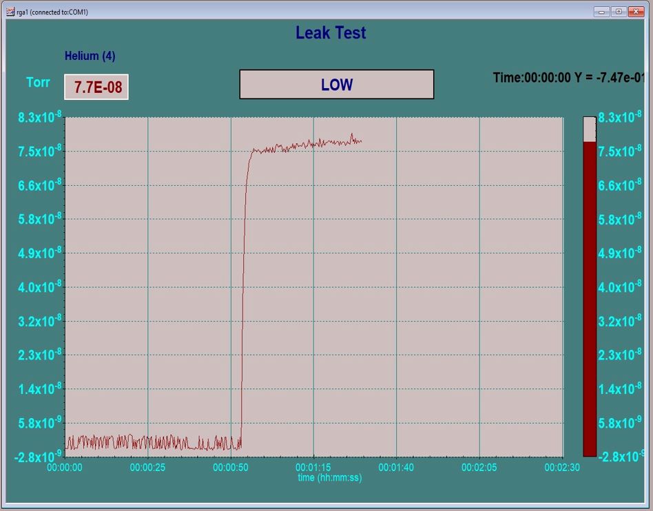
Once you are back to your base vacuum you would set up the RGA in the leak check mode or just scan over the 4 AMU helium peak. Then using helium that is connected through a regulator to a small tube, bleed a small amount of helium over the suspected flanges and feedthroughs while monitoring the helium peak on the RGA. Helium is a very small molecule and so it will pass into the leak and then be detected by the RGA. For best results I have found that you need to close off your pumps (or turn off your ion pump) while leak checking with helium. Just keep an eye on your vacuum and make sure that you pump out the chamber periodically to keep the vacuum at least in the 10-6 Torr or better. When you find the leak with helium you will see an immediate and dramatic change in the RGA scan (as shown below). It will be easy to confirm the location of the leak by pumping out the helium and then repeating the experiment.
RGA Leak test Helium
For large industrial vacuum chambers portable leak checkers are available so that the chamber does not need to be vented to install the RGA.
What happens if you can’t find a leak? In the case of high vacuum leaks if you can’t find a leak, there may not be a leak. Sometimes what appears to be a leak is really just a whole lot of water vapor, a virtual leak or possibly hydrocarbon contamination. In these cases, a very long bake out should solve the problem. Long as in 24 or 36 hours at 150 to 200 degrees Celsius.
RGAs start at about $3,500.00 and go up from there depending on Mass range, multiplier and energy filter options. Here are some links to RGA companies –
Once you do find the leak you may need to remove water vapor from the chamber in order to obtain a better base vacuum. A number of water vapor desorption options are available from RBD Instruments at this link – Water Vapor Desorption