This post is a compilation of information that we have provided in some of our newsletters about the Physical Electronics 11-010 electron gun control. These units are typically found with the 10-150/155 and 15-255G CMA auger and double pass x-ray photoelectron analyzers. As always, refer servicing to personnel trained to work safely with high voltage. The 11-010 contains potentially lethal voltages and currents! RBD Instruments provides repair services on the 11-010 electron gun control.
11-010 electron gun control basic operation:
1. Turn Emission voltage knob fully CW and the Filament current knob fully CCW.
2. Turn on the main power switch.
3. Turn beam voltage on, set it to Zero KV
4. Turn up filament knob until you have 1 mA of emission current.
5. Allow the filament to warm up, then increase to no more than 2 mA of emission current. Keeping the emission current at 1mA will length the analyzer filament lifetime.
6. If necessary, adjust the filament current limit pot (P1) so that you have no more than 2 mA of emission with the emission fully CW. This should happen at 6-7 turns of the filament pot. (Caution! The emission board is floating on the high voltage. Set the beam voltage to Zero kV before adjusting the filament current limit.)
7. Once the filament has stabilized, turn on the beam voltage to 2kV and reduce the emission voltage knob from fully CW to slightly CCW and obtain the best looking elastic peak. Also adjust the focus on the 11-010 as needed for optimal counts and peak shape.
Tech Tip: Setting your 11-010 Electron Gun Control with low enough current to run the 15-255G analyzer in pulse count mode
Set the emission current.
1. On your 11-010 electron gun control, set the emission knob fully CW.
2. Turn the beam voltage on and set it to 2 kV.
3. Slowly turn up the filament knob until you have 1 mA of emission current (about 7 turns on the knob). It will take a few minutes for the emission to stabilize. After it levels off, set it to no more than 2 mA.
Note: Never exceed 2mA of emission current or else the filament lifetime may be significantly shortened.
Set the emission current low enough for pulse count mode:
1. Turn the emission current knob fully CCW.
2. Turn the filament current knob ½ turn CCW
Note: This will be approx. 100nA of beam current
11-010 System Emission Calibration:
1. Turn beam voltage on, set to Zero KV
2. Turn Emission knob fully CW
3. Turn up filament knob until you have 2 mA of emission
4. If necessary, adjust the filament current pot so that you have no more than 2 mA of emission with the emission fully CW. This should happen at 6-7 turns of the filament pot.
11-010 Repair & Calibration
In General
This unit runs hot! The bottom plate should be vented to provide adequate ventilation.
Power Supplies
+90 Vdc +/- 10 Vdc (<30 mVac) at CR24 cathode, ref. to chassis
-90 Vdc +/- 10 Vdc (<30 mVac) at CR22 anode, ref. to chassis
+15 Vdc +/- .5 Vdc (<10 mVac) at any op-amp pin 7, ref. to chassis
-15 Vdc +/- .5 Vdc (<10 mVac) at any op-amp pin 4, ref. to chassis
BV Interlock
Short pins A & C together to turn off the power remotely.
Filament Supply
Rotate the filament current knob to the counterclockwise limit before applying power.
There are two over-current protection circuits. The filament current potentiometer limits the current to 3.45 amps and the large wire wound resistor is a backup that limits (by shutting the 11-010 off)at 3.6 to 3.8 amps. To measure the filament current, connect a 5 amp ammeter between F1 and F2. Note: adjust the backup over-current sense first.
1. Adjusting both the filament knob on the front panel and the pot on the filament board to obtain enough current to trigger the backup over-current sense, set the wire wound resistor wiper so that the unit shuts down between 3.6 and 3.8 amps. Reset the 11-010 by turning the power off, then on again.
2. Adjusting the filament knob on the front panel until the first current limit is reached (not the backup), set the pot on the filament board so that the current limits at 3.45 amps.
Emission Supply
Note that the emission supply only turns on when the beam voltage is also on. Rotate the emission current knob to the counterclockwise limit before applying power.
1. Connect a 10 watt 8 Kohm resistor between F1 and V1. Measure and note its actual resistance. Isolate it well since it floats at the beam voltage.
2. Turn on BV (set to zero). Rotate the emission knob clockwise to its maximum. Calculate the current through the resistor be measuring the voltage across it. The meter should read approximately 6.25 mA (based on 50V of emission voltage).
3. Turn off the BV with the emission still on. The meter should drop to zero.
Beam Voltage
1. Use a high voltage probe (5 kV) to measure the voltage at F1 referenced to chassis ground.
2. Set the BV to 2 kV (Caution – high voltage is present!) and turn the Fine knob fully counterclockwise to the CAL position.
3. Turn on the BV. You should read 2 kVdc +/- 1 Vdc. If not adjust the pot on the HV board for 2kV.
Focus Voltage (V2)
The focus voltage should be adjustable (using the focus knob) from approximately 65% to 95% of the beam voltage.
Deflection
The BV does not need to be on for this test. The deflection output consists of DC offset signals (no waveforms) that vary from approximately -65 Vdc to +65 Vdc. The ripple should be less than 100 mVac. The signals do not necessarily correspond to the knob setting. Press the deflection power button to turn on.
1. Note the voltage at pins A and B as the X Deflection knob is adjusted to the limits. A and B are inverses of each other and each varies over the entire range.
2. Do the same for pins C and D by adjusting the Y Deflection knob.
3. Set the deflection pots for zero volts on the deflection output pins.
Troubleshooting Tips
1. Check for glowing filaments in the vacuum tubes when the power is turned on. A “cold” tube typically indicated either a bad tube or a bad connection at its base.
2. It is common for some of the 741 op-amps to blow in the deflection circuitry. Check those first if the deflection doesn’t operate properly.
11-010 Troubleshooting:
Problem: Blowing fuses when High Voltage is turned on.
Possible cause: High Voltage transformer shorted
Troubleshoot: Disconnect transformer output wires from circuit board.
Start with the Primary, then to the Secondary, to see if fuses still blow.
Problem: Filament Cut off circuit not working.
Possible Causes: Bad Opto-Isolator, Bad MPS3704, or I’ve now seen an open path on the floating ground cause this so check the resistance between the ground path on the HV circuit with Pin 14 or the tap on the 1 ohm resistor.
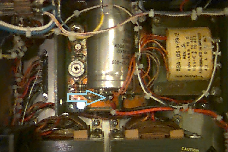
11-010 Emission Current Noise Reduction Modification
Due to aging components, many of the PHI 11-010 5 kV electron gun controls have developed a slight noise problem in the emission “chopper” circuit on the 623 board. This results in about 300 mV of 60 Hz ripple on the emission voltage, which translates into noise in the electron beam and Auger data.
Since the “chopper” circuit is never used (it was designed as a way to get N/E data with a lock-in recorder), a very simple solution to the problem is to simply bypass this circuit.
Procedure:
1. Unplug the 11-010 AC power cord and remove the cover.
2. Solder a jumper between Pins 17 and 18 on the 623 board . (The 623 board is located on the side of the 11-010, just above the filament supply board.)
This modification will reduce the noise level from about 300 mV to 50 mV or less and results in noticeably cleaner Auger data.
279905_11-010_Electron_Gun_Control_Component_Manual