A blog on the repair, operation and calibration of surface analysis systems and components including electron spectrometers, sputter ion guns and vacuum related hardware. Click on the Index tab below to see a list of all posts. Visit our website at http://www.rbdinstruments.com
The latest software releases of Actuel for the 9103 Picoammeter and CMapp for the microCMA now support the ability to automatically read target current when acquiring data.
To use this feature, you must (of course) have a 9103 Picoammeter running RBD’s Actuel software.
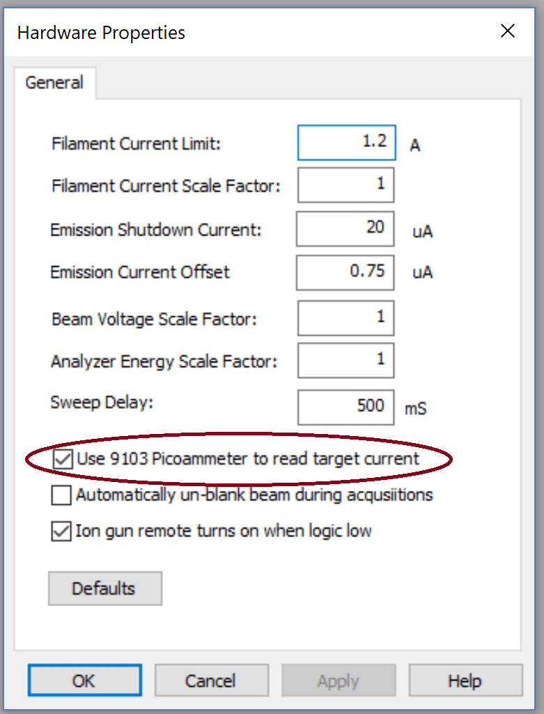
Run CMapp for the microCMA, select Hardware Properties from the System menu, and check the option “Use 9103 Picoammeter to read target current.” You only have to do this once.
Turn on the 9103 Picoammeter, run Actuel, and measure your target current as usual. Leave Actuel open. It doesn’t matter whether the 9103 is sampling, but keep in mind that your current settings (sample rate, etc.), will be used.
Now, whenever you take an acquisition (except for an alignment), the target current will be measured at the beginning of the acquisition and displayed with the other electron gun settings when the acquisition is complete.
If you don’t have a 9103, you can still manually enter a value for the target current in the acquisition dialog.
Download the latest release of Actuel for the 9103 Picoammeter here.
Download the latest release of CMapp for the microCMA here.
If you run multiple USB devices that operate as virtual RS232 COM ports (the ubiquitous serial port standard) on Windows, you may have run into problems with conflicts between devices. An application may connect to the appropriate device when it’s the only one connected, only to “get confused” if there is another device sharing the PC. Happily, there are a few simple things you can try that will often resolve the problem.
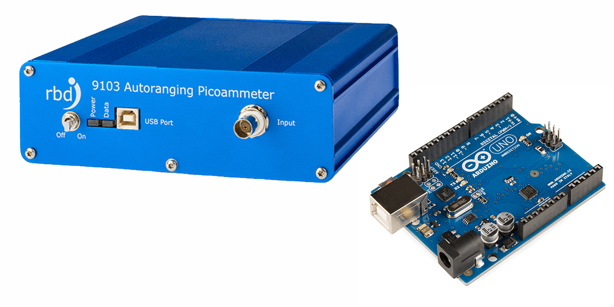
9103s and Arduinos Playing Nice Together
A 9103 Picoammeter and Arduino
To most Windows applications, virtual COM ports (VCPs) all look the same. An application can open a port and and attempt to communicate with the connected device, but since there’s no fixed protocol – each device speaks its own “language”, any message sent can have undetermined effects if the device you’re communicating with is not the one your were expecting. Some applications simply connect to the first COM port available, other’s may provide a way to select the COM port your device is connected to – but you’re still responsible for figuring that out.
When manufacturers produce hardware for PCs they can apply for unique vendor ad product IDs for their device, and there are ways for applications to safely query these. But that only solves part of the problem. Many devices use third-party USB chips and drivers from companies like FTDI, so they share the same IDs. These devices look the same to a Windows client application, or to a person perusing the Device Manager in Control Panel.
RBD’s own 9103 Picoammeter utilizes FTDI’s popular USB VCP chips, as do many versions of the popular Arduino microcontroller boards, so these two sets of devices can be confused by client applications when used on the same PC. And s it turns out, they are often used together. Here are a few tricks for getting these device to play nice together.
Solution 1: Connect Each Device and Run Each Client in Order
Many applications require you to specify the port for the selected device. Others (like Actuel for the 9103) poll the COM ports in numerical order and check and connect to the first available. If these devices first check the vendor and product ID (like the 9103), they will at least skip ports that do not match. But they cannot distinguish between two devices using the same USB chip (like FTDI’s). Setting up a device connection / application order can solve this.
In the case of a 9103 / Arduino conflict, remove all other devices, then plug in the 9103 and power it on. Next run the Actuel software. The software will find and take control of the 9103 port, and once assigned, you can safely plug in the next device and run its client.
Another order might make more sense for your particular application. Experiment with your configuration, and there are more than two devices, try getting two working first. Document the process and just make sure it’s followed anytime you reboot / power-on.
Solution 2: Change the COM Port Number for a Particular USB Port
You can force Windows to use a different COM port number than the one automatically assigned. This may help with applications that select the lowest numbered port.
For example, if the 9103 is connected to COM4 and another FTDI device is on COM3, the 9103 client software may incorrectly select the device on COM3. Setting the 9103 to COM2 may allow you to now connect the devices and run the client applications in any order, depending on how those other devices / applications behave. Some experimentation may be necessary.
With the 9103 connected and turned on, run Control Panel / Device Manager, and find the selection for “Ports (COM and LPT)”, click and you should see an entry for “USB Serial Port (COM4)” (the COM# may be different of course). Double-click for properties.
The COM port settings for the 9103
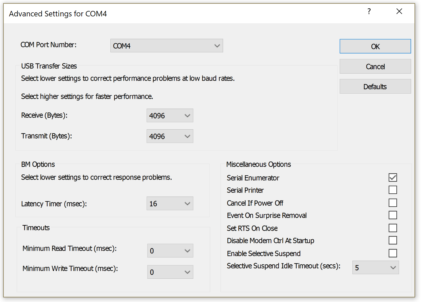
Now select the “Port Settings” tab, and click the “Advanced…” button. From this window you can select a new COM port assignment:
Choosing a COM port for the 9103
Keep in mind that plugging a device into different USB port will change the COM port assigned to it.
More Info
Of course, you’ll want to ensure you have the latest drivers installed. For FTDI, they can be found here:
If you’re thinking of programming your own serial port application, here’s a quick tutorial at the API level. Many popular languages include code for VCP programming, and third-party libraries are available:
A new feature has been added to AugerScan – the option to automatically mark all the peaks of a particular Auger element when marking the primary peak. With this feature you can mark an element’s primary peak and AugerScan will automatically mark the rest of the element’s peaks and select the primary for atomic concentration.
An Example Using Copper (Cu1)
AugerScan – Marking multiple peaks for copper (Cu1)
In the example above, we’ve selected the carbon (C1), oxygen (O1) and copper (Cu1) peaks. AugerScan automatically marked the additional copper peaks (Cu2, Cu3, and Cu4). When performing an atomic concentration calculation, only the Cu1 peak is selected.
You can of course easily change which peaks are selected for atomic concentration by clicking the “Markers” command from the “Edit” menu. You can also remove selected markers from peaks using this dialog.
AugerScan – Marker Selection Dialog
To turn this feature on/off, choose the “Options…” command from the “Data” menu, and select/deselect the checkbox labeled “When Marking and Element, Mark all of its Peaks”.
AugerScan – Marking all Peaks Option
(This feature was originally developed for CMapp, RBD’s software for the microCMA Compact Auger Analyzer)